
Bone fusion device

一种骨融合、期望位置的技术,应用在椎骨的装置领域,能够解决长恢复时期等问题

Active Publication Date: 2018-01-16
NEUROPRO TECH
View PDF24 Cites 3 Cited by
  • Summary
  • Abstract
  • Description
  • Claims
  • Application Information

AI Technical Summary

Problems solved by technology

Such invasive surgical procedures require a long recovery period

Method used


Image

  • Bone fusion device
  • Bone fusion device
  • Bone fusion device

Examples


Embodiment Construction

[0069] In the following description, numerous details and alternatives are set forth for purposes of explanation. It will be recognized, however, by those skilled in the art that the present invention may be practiced without the use of these specific details. For example, the following figures and descriptions often refer to the vertebrae of the spine. However, those skilled in the art will recognize that some embodiments of the present invention are practiced with respect to the fusion of other bones, including broken bones and / or joints. In other instances, well-known structures and devices are shown in block diagram form in order not to obscure the description of the present invention with unnecessary detail.

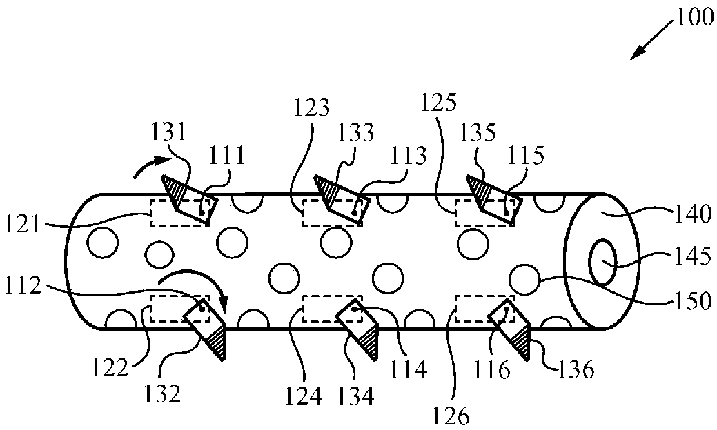
[0070] figure 1 Illustrated is a bone fusion device 100 according to some embodiments of the invention. As shown in this figure, the bone fusion device 100 has a round cylindrical shape and has two end faces, including end face 140 . In some embodiments, bone fu...


PUM


Abstract

A bone fusion device provides stability to bones during a bone fusion period. The bones include, for example, the vertebrae of a spinal column. The bone fusion device comprises one or more extendabletabs attached to the bone fusion device by associated rotating means. The bone fusion device is preferably inserted by using an arthroscopic surgical procedure. During arthroscopic insertion of the device, the tabs are pre-configured for compactness. In this compact configuration, the tabs are preferably deposed along and / or within an exterior surface of the bone fusion device. After the bone fusion device has been positioned between the bones, one or more tab(s) are extended. In the preferred embodiment, the position of each tab is related to a positioning element and extending blocks. Typically, the tabs advantageously position and brace the bone fusion device in the confined space between the bones until the bones have fused.

Description

[0001] This application is a divisional application of a Chinese patent application with application number 201380040119.5 and titled "bone fusion device" filed on May 21, 2013. [0002] related application [0003] This application is a continuation-in-part of co-pending U.S. Patent Application Serial No. 11 / 484,379, filed July 10, 2006, and entitled "BONE FUSION DEVICE," which A continuation-in-part of U.S. Patent No. 7,727,280, issued June 1, 2010, entitled "BONE FUSION DEVICE," which is an abandoned U.S. Patent entitled "BONE FUSION DEVICE," filed November 1, 2005 Application Serial No. 11 / 264,958 is continued in part and based on 35 U.S.C. §119 (e) of expired U.S. Provisional Patent Application Serial No. 60 / 624,836, filed November 3, 2004 and entitled "BONE FUSION DEVICE" Priority is claimed, all of which are hereby incorporated by reference. Furthermore, this application claims priority based on 35 U.S.C. §119 (e) of U.S. Provisional Patent Application Serial No. 61 / 624...

Claims


Application Information

Patent Timeline
Patent Type & Authority Applications(China)
IPC IPC(8): A61F2/44A61F2/46
CPCA61B2017/0256A61F2/4455A61F2/446A61F2/447A61F2/4611A61F2002/2817A61F2002/2835A61F2002/30266A61F2002/30411A61F2002/30492A61F2002/30505A61F2002/30507A61F2002/30525A61F2002/30528A61F2002/30538A61F2002/30556A61F2002/30565A61F2002/30579A61F2002/30777A61F2002/30784A61F2002/30841A61F2002/3085A61F2002/30904A61F2002/3092A61F2002/4627A61F2002/4629A61F2220/0025A61F2250/0006A61F2250/0009A61F2310/00023A61F2310/00976A61B2090/061A61B2090/0811A61B17/70A61F2002/2832A61F2250/0025
Inventor G.R.麦克卢恩B.J.雷明顿D.R.巴克J.N.洛冈G.C.斯塔尔库普
Owner NEUROPRO TECH
Features
  • Generate Ideas
  • Intellectual Property
  • Life Sciences
  • Materials
  • Tech Scout
  • Unparalleled Data Quality
  • Higher Quality Content
  • 60% Fewer Hallucinations
Learn More