Angle-adjustable back-pounding machine

A technology of angle adjustment and driving machine, which is applied in the field of medical equipment, can solve the problems of large space occupation, high price, and inability to adjust angles, etc., and achieve the effects of reducing floor space, improving safety, and improving protection work

Inactive Publication Date: 2018-01-16
周军美
View PDF7 Cites 0 Cited by
  • Summary
  • Abstract
  • Description
  • Claims
  • Application Information

AI Technical Summary

Problems solved by technology

[0002] Modern people will suffer from low back pain due to sitting for a long time without exercising. Severe patients will affect their normal life. In order to relieve the pain, in addition to using plaster and other medicines, they should also beat the low back to dredge the meridians, promote blood circulation and relieve soreness. At present, some hospitals provide special massage and back massage, but the price is expensive. However, some back massage machines on the market are complex in structure, expensive, and take up a lot of space. They generally perform massage in the horizontal direction and cannot adjust the angle according to the arc of the human back. thrashing, bad effect

Method used


Image

  • Angle-adjustable back-pounding machine
  • Angle-adjustable back-pounding machine
  • Angle-adjustable back-pounding machine

Examples


Embodiment Construction

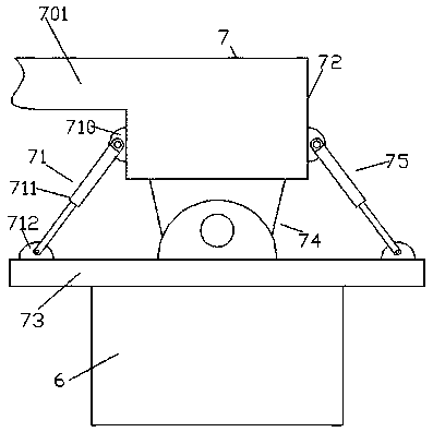
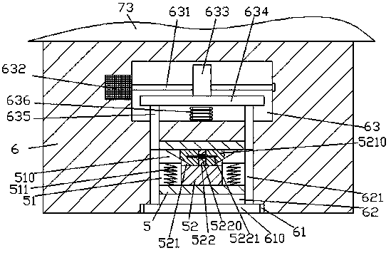
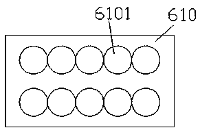
[0016] Such as figure 1 , figure 2 and image 3 As shown, an angle-adjustable back beater of the present invention includes a supporting device 7 and a beating driver 6 fixedly installed on the bottom of the supporting device 7, and a groove 61 is provided in the bottom surface of the beating driver 6, A beating plate 610 is slidingly fitted in the cavity 61 , and the top wall of the cavity 61 is connected with a first cavity 62 extending upwards, and the knocking drive on the upper side of the first cavity 62 The machine 6 is provided with a second cavity 63, the second cavity 63 is provided with a beating drive device, and the first cavity 62 is slidingly connected with a sliding block 5 that is connected to the beating drive device. , the left and right sides of the sliding joint block 5 are slidingly connected with push connecting rods 621 extending up and down. The top surface of the plate 610 is fixedly connected, and the sliding block 5 is provided with a connecting...


PUM


Abstract

The invention discloses an angle-adjustable backbeating machine, which comprises a supporting device and a beating driver fixedly installed at the bottom of the supporting device, a groove is arranged on the bottom surface of the beating driver, and a beating plate is slidingly connected in the groove to accommodate The top wall in the groove is connected with a first cavity extending upwards, and a second cavity is provided in the beating driver on the upper side of the first cavity, and a beating drive device is arranged in the second cavity, and the first cavity The inner sliding joint is equipped with a sliding joint block that is connected with the beating drive device. The left and right sides of the sliding joint block are slidingly jointed with push rods that extend up and down. The bottom extension tail of each push rod is inserted into the container And it is fixedly connected with the top surface of the beating plate, and the sliding block is provided with connecting grooves arranged through the left and right sides; the invention has simple structure, convenient operation, improves the safety of beating work, and at the same time, improves beating efficiency and beating effect.

Description

technical field [0001] The invention relates to the field of medical equipment, in particular to an angle-adjustable back beater. Background technique [0002] Modern people will suffer from low back pain due to sitting for a long time without exercising. Severe patients will affect their normal life. In order to relieve the pain, in addition to using plaster and other medicines, they should also beat the low back to dredge the meridians, promote blood circulation and relieve soreness. At present, some hospitals provide special massage and back massage, but the price is expensive. However, some back massage machines on the market are complex in structure, expensive, and take up a lot of space. They generally perform massage in the horizontal direction and cannot adjust the angle according to the arc of the human back. Thumping, the effect is not good. Contents of the invention [0003] The technical problem to be solved by the present invention is to provide an angle-adju...

Claims


Application Information

Patent Timeline
Patent Type & Authority Applications(China)
IPC IPC(8): A61H23/02
Inventor 周军美
Owner 周军美
Why Eureka
Try Eureka