Garbage compression device

A technology of garbage compression and pressure rods, applied in the direction of presses, stamping machines, manufacturing tools, etc., can solve the problems of low efficiency, difficult operation, high cost of use, etc., to reduce floor space, improve protection work, and improve safety sexual effect

Inactive Publication Date: 2018-06-29
韦健敏
View PDF6 Cites 0 Cited by
  • Summary
  • Abstract
  • Description
  • Claims
  • Application Information

AI Technical Summary

Problems solved by technology

[0002] With the continuous enhancement of people's awareness of environmental protection, household garbage has been sorted and stored for secondary recycling and processing. In some large garbage recycling stations, some highly plastic household garbage such as (pop cans, plastic bottles, etc.) need to be cleaned before processing It performs compression treatment to reduce the volume. In the traditional technology, the compression treatment of garbage is generally through manual extrusion. The operation is difficult and inefficient, and it is difficult to meet the processing needs. There are also many automatic garbage compression devices in the existing technology. However, its structure is complex, the cost of use is high, and it can only be compressed in the vertical direction, and cannot be compressed from an inclined plane, resulting in a small garbage height but a large width, and a large garbage footprint

Method used


Image

  • Garbage compression device
  • Garbage compression device
  • Garbage compression device

Examples


Embodiment Construction

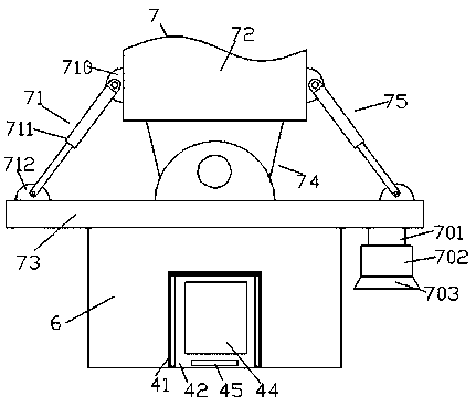
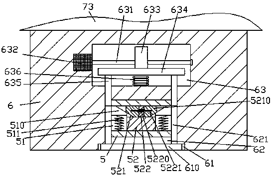
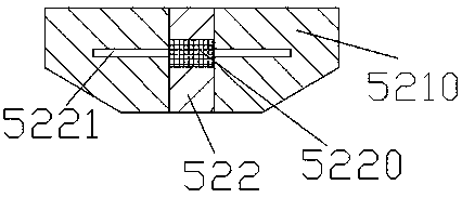
[0017] Such as figure 1 , figure 2 and image 3 As shown, a garbage compression device of the present invention includes a lifting device 7 and a compression driving machine 6 fixedly installed at the bottom of the lifting device 7, and an empty groove 61 is arranged in the bottom surface of the compression driving machine 6. A compression plate 610 is slidingly fitted in the hollow groove 61, and the top wall of the hollow groove 61 is connected with a first cavity 62 extending upward. 6 is provided with a second cavity 63, the second cavity 63 is provided with a compression and displacement device, and the first cavity 62 is slid and connected with a sliding block 5 that is connected with the compression and displacement device. The left and right sides of the sliding block 5 are slid and connected with push rods 621 extending up and down. 610, the top surface is fixedly connected, and the sliding block 5 is provided with a through groove 51 arranged through the left and...


PUM


Abstract

The invention discloses a garbage compression device. The garbage compression device comprises a lifting device and a compression driver fixedly mounted in the bottom of the lifting device, wherein anempty slot is formed in the bottom surface of the compression driver; a compression plate is slidably connected in the empty slot in a matched manner; a first cavity extending upward is formed through the top wall of the empty slot; a second cavity is formed in the compression driver on the upper side of the first cavity; a compression driving device is arranged in the second cavity; a slide block connected to the compression driving device in a matched manner is slidably connected to the first cavity in a matched manner; push rods extending up and down are slidably connected to the left andright sides of the slide block in a matched manner; the extended tail end of each push rod extends into the empty slot and is fixedly connected to the top surface of the compression plate; and a through slot is left and right formed through the slide block. The garbage compression device disclosed by the invention is simple in structure and convenient to operate, and the compression work safety isimproved and meanwhile, the compression efficiency and compression effect are improved.

Description

technical field [0001] The invention relates to the technical field of domestic garbage compression, in particular to a garbage compression device. Background technique [0002] With the continuous enhancement of people's awareness of environmental protection, household garbage has been sorted and stored for secondary recycling and processing. In some large garbage recycling stations, some highly plastic household garbage such as (pop cans, plastic bottles, etc.) need to be cleaned before processing It performs compression treatment to reduce the volume. In the traditional technology, the compression treatment of garbage is generally through manual extrusion. The operation is difficult and inefficient, and it is difficult to meet the processing needs. There are also many automatic garbage compression devices in the existing technology. However, its structure is complex, its use cost is high, and it can only be compressed in the vertical direction, and cannot be compressed fr...

Claims


Application Information

Patent Timeline
Patent Type & Authority Applications(China)
IPC IPC(8): B30B1/26B30B9/00B30B15/00B30B15/28B09B3/00
CPCB30B1/261B09B3/00B30B9/00B30B15/00B30B15/28
Inventor 韦健敏
Owner 韦健敏
Why Eureka
Try Eureka