
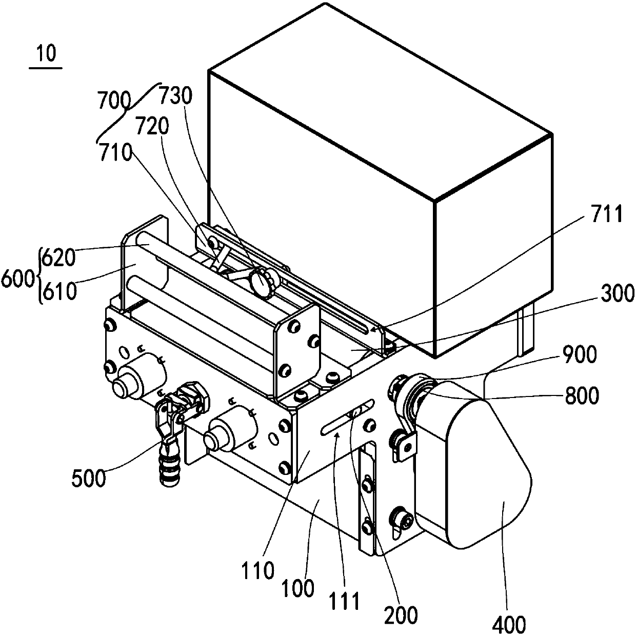
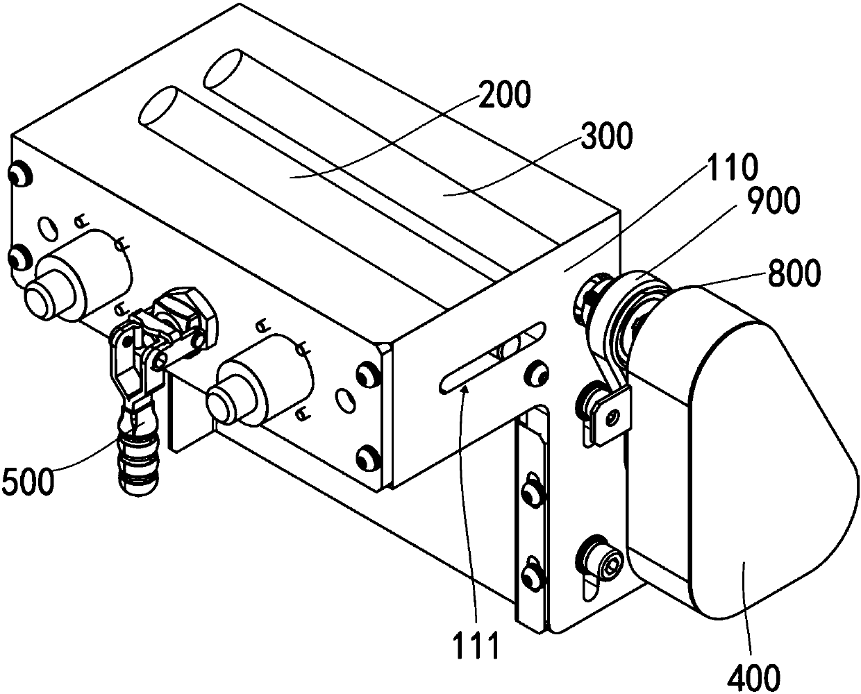
Automatic yarn pulling mechanism for batch warping machine

A warping machine, automatic technology, applied in the textile field, can solve the problems of low efficiency, time-consuming and laborious, large workload, etc.

Pending Publication Date: 2018-01-16
GUANGDONG ESQUEL TEXTILES CO LTD
View PDF6 Cites 1 Cited by
  • Summary
  • Abstract
  • Description
  • Claims
  • Application Information

AI Technical Summary

Problems solved by technology

The workload of manual yarn drawing is large, time-consuming and laborious, and the efficiency of manual yarn drawing is low

Method used


Image

  • Automatic yarn pulling mechanism for batch warping machine
  • Automatic yarn pulling mechanism for batch warping machine

Examples


Embodiment Construction

[0023] In order to facilitate the understanding of the present invention, the present invention will be described more fully below with reference to the associated drawings. Preferred embodiments of the invention are shown in the accompanying drawings. However, the present invention can be embodied in many different forms and is not limited to the embodiments described herein. On the contrary, these embodiments are provided to make the understanding of the disclosure of the present invention more thorough and comprehensive.

[0024] It should be noted that when an element is referred to as being “fixed” to another element, it can be directly on the other element or there can also be an intervening element. When an element is referred to as being "connected to" another element, it can be directly connected to the other element or intervening elements may also be present.

[0025] Unless otherwise defined, all technical and scientific terms used herein have the same meaning as...


PUM

PropertyMeasurementUnit
Shore hardnessaaaaaaaaaa

Abstract

The invention discloses an automatic yarn pulling mechanism for a batch warping machine. The automatic yarn pulling mechanism comprises a stander, a transmission roll, a pressure roll, a driving device and a clamping device, wherein adjusting channels are formed two opposite sides of the stander, the transmission roll is hinged to the stander, two ends of the pressure roll are respectively locatedin the adjusting channels, the pressure roll can move in the adjusting channels, and a gap for yarns to pass through is formed between the pressure roll and the transmission roll; the driving deviceis arranged on the stander and is connected to the transmission roll and is used for driving the transmission roll to rotate; and one end of the clamping device is connected to the stander, the otherend of the clamping device props against the pressure roll, and the clamping device is used for pressing the pressure roll towards the transmission roll. The automatic yarn pulling mechanism for the batch warping machine has the beneficial effects that the time and the force are saved, and the yarn pulling efficiency is high.

Description

technical field [0001] The invention relates to the textile field, in particular to an automatic yarn drawing mechanism of a batch warping machine. Background technique [0002] When the warping machine is produced in batches, a section of yarn must be pulled out before the raw yarn is ready for production, and its function is to pull away the rotten yarn and broken yarn on the surface of the raw yarn. At present, the yarn drawing during batch warping machine production is manually pulling about 900 ends of the yarn, and the length of the yarn that needs to be drawn is about 100 meters. The workload of manual yarn drawing is large, time-consuming and laborious, and the efficiency of manual yarn drawing is low. Contents of the invention [0003] Based on this, it is necessary to provide an automatic yarn drawing mechanism for batch warping machines that saves time and labor and has high yarn drawing efficiency. [0004] An automatic yarn-drawing mechanism of a batch warpi...

Claims


Application Information

Patent Timeline
IPC IPC(8): D02H3/00D02H13/00
Inventor 文长华田柱安王允问晓锋刘细强
Owner GUANGDONG ESQUEL TEXTILES CO LTD
Learn More