Novel combustor tube head structure

A technology of burners and pipe heads, which is applied in the direction of burners, burners burning powder fuel, combustion methods, etc., can solve the problems of burner performance degradation, uneven thermal expansion of pipe heads, displacement of mating surfaces, etc., to ensure stable performance , stable compensation performance, the effect of stable compensation performance

Inactive Publication Date: 2018-01-16
扬州科兴德机械制造有限公司
View PDF0 Cites 0 Cited by
  • Summary
  • Abstract
  • Description
  • Claims
  • Application Information

AI Technical Summary

Problems solved by technology

[0002] The existing head outflow air duct and the head coal air duct were originally machined and matched. Since the burner works in a high-temperature environment, this caused the thermal expansion of the two pipe heads to differ, resulting in a large displacement of the mating surface, resulting in The performance of the burner is reduced and cannot meet the requirements of use

Method used


Image

  • Novel combustor tube head structure

Examples


Embodiment Construction

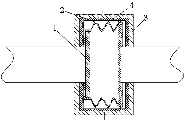
[0014] The two pipe heads 1 of the present invention have a flange structure, and the connection between the two pipe heads 1 is realized by an elastic pipe 2. The connecting head 3, the connecting head 3 and the corresponding pipe head 1 form the positioning of the elastic tube 2, and the two connecting heads 3 are butted to form a fixed connection.

[0015] At the same time, the connecting head 3 forms a limit to the elastic tube 2 from the circumferential direction.

[0016] The elastic tube 2 is in the form of a bellows structure.

[0017] An elastic pad 4 is arranged between the elastic tube 2 and the connecting head 3 .

[0018] The working process of the present invention is as follows: the present invention first clamps the elastic tube 2 on the inner end of the corresponding pipe head 1, then sets the corresponding connecting head 3 on the outer end of the pipe head 1, and the connecting head 3 and the pipe head 1 will elastically The positioning of the tube 2 is fo...


PUM


Abstract

The invention relates to a novel combustor tube head structure. The novel combustor tube head structure is characterized in that two tube heads (1) are of flange structures; the two tube heads (1) areconnected through an elastic pipe (2); two ends of the elastic pipe (2) are clamped on inner ends of the corresponding tube heads (1); the tube heads (1) are sleeved by connectors (3) respectively; the connectors (3) and the corresponding tube heads (1) can position the elastic pipe (2); and the two connectors (3) are fixedly butt-jointed. The telescopic elastic pipe is reserved between the two tube heads; in use, the two tube heads are heated and expanded to form a clearance, and the clearance can be compensated by the elastic pipe; and when the two tube heads shrink, the clearance can be compensated by the elastic pipe.

Description

technical field [0001] The invention relates to a novel burner pipe head structure, which is applied in a coal-fired thermal system. Background technique [0002] The existing head outflow air duct and the head coal air duct were originally machined and matched. Since the burner works in a high-temperature environment, this caused the thermal expansion of the two pipe heads to differ, resulting in a large displacement of the mating surface, resulting in The performance of the burner is reduced and cannot meet the requirements of use. Contents of the invention [0003] The purpose of the present invention is to provide a novel burner pipe head structure which can improve the service performance of the pulverized coal burner. [0004] For this reason, the technical solution adopted by the present invention is: the two pipe heads (1) are in flange structure, and the connection between the two pipe heads (1) is realized through the elastic pipe (2), and the two ends of the el...

Claims


Application Information

Patent Timeline
Patent Type & Authority Applications(China)
IPC IPC(8): F23D1/00
Inventor 袁明涛顾松庆吕文卿丁良
Owner 扬州科兴德机械制造有限公司
Why Eureka
Try Eureka