A wellbore dynamic liquid level monitoring method for drilling and plugging construction

A technology of wellbore and liquid level, which is applied in wellbore/well components, measurement, earth-moving drilling and production, etc., can solve the problems of difficult to truly reflect the plugging slurry and the low success rate of plugging, so as to improve the success rate of plugging and improve the The effect of knowledge and accurate data

Active Publication Date: 2020-07-24
BC P INC CHINA NAT PETROLEUM CORP +1
View PDF10 Cites 0 Cited by
  • Summary
  • Abstract
  • Description
  • Claims
  • Application Information

AI Technical Summary

Problems solved by technology

[0003] In the plugging operation, for the wells where the drilling fluid cannot be returned from the wellhead, since there are no effective dynamic liquid level monitoring tools and methods at present, the position of the dynamic liquid level in the wellbore can only be estimated by replacing the amount of drilling fluid, and by Calculate the position of the plugging slurry in the wellbore and judge the amount of the plugging slurry entering the leaky layer based on this
This method of estimating the position of the plugging slurry in the wellbore by the amount of displacement is often inaccurate, and it is difficult to truly reflect the situation of the plugging slurry in the wellbore, which often leads to the failure of plugging with hydraulic materials such as cement slurry. The success rate of leak plugging is not high

Method used


Image

  • A wellbore dynamic liquid level monitoring method for drilling and plugging construction

Examples


Embodiment 1

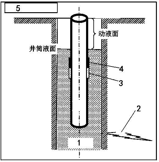
[0021] As a preferred embodiment of the present invention, with reference to the attached figure 1 , this example discloses:

[0022] A wellbore liquid level monitoring method for drilling leak plugging construction, comprising the following steps:

[0023] Step A: Estimate the static liquid level position of the wellbore 1 after the plugging operation is completed according to the pressure of the leaking layer 2 and the selected plugging construction plan;

[0024] Step B: Connect the pressure testing instrument with the plugging drilling tool assembly, and put the connected pressure testing instrument into the wellbore 1, so that the position of the pressure testing instrument in the wellbore 1 is located at the hydrostatic fluid estimated in step A below the face;

[0025] Step C: start the plugging operation, start the pressure testing instrument, and monitor the dynamic liquid level of the wellbore 1 in real time;

[0026] Step D: Calculate the position of the plugging...

Embodiment 2

[0028] As another preferred embodiment of the present invention, with reference to the attached figure 1 , this example discloses:

[0029] A wellbore liquid level monitoring method for drilling leak plugging construction, comprising the following steps:

[0030] Step A: Estimate the static liquid level position of the wellbore 1 after the plugging operation is completed according to the pressure of the leaking layer 2 and the selected plugging construction plan;

[0031] Step B: Connect the pressure testing instrument with the plugging drilling tool assembly, and put the connected pressure testing instrument into the wellbore 1, so that the position of the pressure testing instrument in the wellbore 1 is located at the hydrostatic fluid estimated in step A below the face;

[0032] Step C: start the plugging operation, start the pressure testing instrument, and monitor the dynamic liquid level of the wellbore 1 in real time;

[0033] Step D: Calculate the position of the pl...

Embodiment 3

[0037] As another preferred embodiment of the present invention, with reference to the attached figure 1 , this example discloses:

[0038] A wellbore 1 fluid level monitoring method for drilling plugging construction, comprising the following steps:

[0039] Step A. Estimate the static liquid level position of the wellbore 1 after the plugging construction operation is completed according to the pressure of the leaking layer 2 and the selected plugging construction plan;

[0040] Step B: Connect the pressure testing instrument with the plugging drilling tool assembly, and put the connected pressure testing instrument into the wellbore 1, so that the position of the pressure testing instrument in the wellbore 1 is located at the hydrostatic fluid estimated in step A below the face;

[0041] Step C: start the plugging operation, start the pressure testing instrument, and monitor the dynamic liquid level of the wellbore 1 in real time;

[0042] Step D: Calculate the position ...


PUM


Abstract

The invention discloses a wellbore dynamic fluid level monitoring method for drilling lost circulation control construction, which relates to the technical field of petroleum and natural gas drillinglost circulation control construction operation. According to lost circulation zone pressure and a chosen lost circulation control construction scheme, the method estimates a static fluid level in a wellbore after lost circulation control construction operation is completed; a pressure tester is put into the wellbore, and enabling the pressure tester to be below the estimated static fluid level inthe wellbore; the pressure tester is started to monitor the dynamic fluid level of the wellbore in real time; according to monitored wellbore dynamic fluid level condition, the position of lost circulation control fluid in the wellbore is worked out, and the amount of lost circulation control fluid getting into a lost circulation zone is worked out. The method can keep track of the amount of thelost circulation control fluid getting into the lost circulation zone in real time, consequently, lost circulation control construction operation can meet the requirement of a lost circulation controlconstruction design, the success rate of lost circulation control can be increased to the max, and in particular, the success rate of lost circulation control of hydraulic materials, such as cement paste, can be increased.

Description

technical field [0001] The invention relates to the technical field of oil and gas drilling, in particular to the technical field of oil and gas drilling plugging construction operations, and more specifically relates to a wellbore fluid level monitoring method for drilling plugging construction. Background technique [0002] In the process of exploration and development of oil and natural gas resources, in order to better promote the implementation of drilling and workover construction tasks, in these two construction processes, the working fluid in the well often leaks into the formation, which is the so-called Lost circulation, generally speaking, lost circulation often occurs during oil and gas drilling operations. If there is a lost circulation problem, not only will a large amount of drilling fluid be lost, but also the drilling construction cannot be carried out normally, resulting in a large amount of economic and time loss. Therefore, once the well leakage problem ...

Claims


Application Information

Patent Timeline
Patent Type & Authority Patents(China)
IPC IPC(8): E21B47/047E21B47/06E21B33/13
Inventor 马光长冯学荣肖沣峰何劲漆梅
Owner BC P INC CHINA NAT PETROLEUM CORP
Why Eureka
Try Eureka