A Fixing Method for Fluorescent Temperature Measuring Sensor Inside Transformer

A temperature measurement sensor and transformer technology, applied in the field of power transformers, can solve the problems of damage, easy to be broken, torn off, complex structure, etc. of the fluorescent temperature measurement sensor, and achieve the effects of reliable fixation, overcoming easy damage, and improving the success rate.

Active Publication Date: 2019-10-11
BAODING TIANWEI XINYU TECH DEV +1
View PDF3 Cites 0 Cited by
  • Summary
  • Abstract
  • Description
  • Claims
  • Application Information

AI Technical Summary

Problems solved by technology

However, due to the complex structure of the fluorescent optical fiber temperature sensor, and it is easy to be broken, pulled off, etc., if the optical fiber sensor cannot be fixed reliably, there will be serious hidden dangers, because in the overall package of the transformer, body assembly, drying treatment, and final assembly During the process, it is very likely to cause damage to the fluorescent temperature sensor, such as: pulling, squeezing, collision, etc. The existing technology has not solved the above problems well

Method used


Image

  • A Fixing Method for Fluorescent Temperature Measuring Sensor Inside Transformer
  • A Fixing Method for Fluorescent Temperature Measuring Sensor Inside Transformer
  • A Fixing Method for Fluorescent Temperature Measuring Sensor Inside Transformer

Examples


Embodiment 1

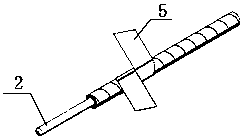
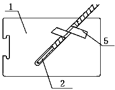
[0029] Embodiment one, with reference to the attached figure 1 , 2 , 5.

[0030] For the fluorescent temperature measuring sensor without a buckle, make an insulating paper tape 5; apply adhesive 10mm from the end of the fluorescent temperature measuring sensor, wrap the fluorescent temperature measuring sensor 2 with insulating paper tape 5, and do not cover the fluorescent temperature measuring sensor. The end of the temperature sensor; then paste the excess part of the insulating paper tape on the insulating standard part 1, and finally paste a 1mm thick insulating cardboard 4 on the top and bottom of the standard insulating part. The shape of the insulating cardboard is the same as that of the standard insulating part Consistent, and press the two layers of insulating cardboard together with the standard insulating part; form the insulating cardboard with the fluorescent temperature sensor and the standard insulating part combination 7.

Embodiment 2

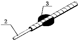
[0031] Embodiment two, referring to the attached image 3 , 4 , 5.

[0032] For the fluorescent temperature measuring sensor with its own buckle, make a slot 3 that matches the buckle; fix the buckle of the fluorescent temperature sensor 2 in the slot 3, and fix the slot on the standard insulator 1. A 1mm thick insulating cardboard 4 is pasted on the top and bottom of the standard insulating part respectively. The shape of the insulating cardboard is consistent with that of the standard insulating part, and the two layers of insulating cardboard are pressed together with the standard insulating part; Combination of insulating cardboard and standard insulating parts7.

[0033] Place the insulating cardboard with the fluorescent temperature sensor and the standard insulator combination 7 in the transformer winding to complete the fixation of the fluorescent temperature sensor inside the transformer.

Embodiment 3

[0034] Embodiment three, with reference to the attached Figure 6 , 7 .

[0035] This standard insulation is the same shape and size as the original insulation standard used in the transformer windings.

[0036] For pie-type windings and spiral windings, the installation of the fluorescent temperature sensor is completed after the winding is completed and before the winding is compacted and shaped; the insulating cardboard with the fluorescent temperature sensor and the standard insulator assembly 7 are placed on the winding wire cake 6, replace the insulation standard parts in the original position between the winding wire cakes.


PUM


Abstract

The invention relates to a method for fixing a fluorescent temperature measuring sensor inside a transformer, belonging to the technical field of power transformers. The technical solution is: first process different insulation standard parts according to different winding types, and then select the fixing method according to the fluorescent temperature sensor, fix the sensor on the insulation standard part, and then paste a 1mm thick insulation on the top and bottom of the insulation standard part. Cardboard and press tight. Finally, the installation time of the combination of insulating cardboard with fluorescent temperature sensor and standard insulating parts is determined according to different winding types. The positive effects of the present invention are: ensure the reliable fixing of the fluorescent temperature measuring sensor, avoid damage to the fluorescent temperature measuring sensor during the whole production process of the transformer, effectively protect the fluorescent temperature measuring sensor, and improve the installation efficiency of the fluorescent temperature measuring sensor on the transformer winding. The success rate overcomes the shortcomings of the original fixing method that the optical fiber is easily damaged, and improves the success rate of the installation of the fluorescent optical fiber temperature sensor on the transformer winding.

Description

technical field [0001] The invention relates to a method for fixing a fluorescent temperature measuring sensor inside a transformer, belonging to the technical field of power transformers. Background technique [0002] For oil-immersed power transformers, when the load or ambient temperature is too high, or when the cooling oil channel inside the winding is blocked, the winding temperature of the transformer will rise abnormally. At this time, the transformer will be exposed to a certain degree of danger. The highest temperature in a certain part of the transformer winding is called the hot spot temperature of the transformer. Once the hot spot temperature exceeds the limit temperature of the transformer insulation, it will cause insulation aging or insulation damage, shorten the life of the transformer, and even damage the body. [0003] In recent years, optical fiber technology has been developed rapidly and widely used, and the application of optical fiber in the field o...

Claims


Application Information

Patent Timeline
Patent Type & Authority Patents(China)
IPC IPC(8): H01F27/40G01K11/32G01K11/3213
Inventor 冀增华何平范辉高树国刘宏亮王宁
Owner BAODING TIANWEI XINYU TECH DEV
Why Eureka
Try Eureka