Three-degree-of-freedom spherical rotor ultrasonic motor stator base and excitation method thereof

A technology of spherical rotor and ultrasonic motor, which is applied in the direction of generator/motor, piezoelectric effect/electrostrictive or magnetostrictive motor, electrical components, etc. It can solve the problems of less driving feet, difficult miniaturization, complex structure, etc. , to achieve the effects of simple structure, easy miniaturization, and easy mass production

Active Publication Date: 2018-01-19
HARBIN INST OF TECH
View PDF4 Cites 2 Cited by
  • Summary
  • Abstract
  • Description
  • Claims
  • Application Information

AI Technical Summary

Problems solved by technology

[0004] The present invention aims to solve the problems that the existing multi-degree-of-freedom rotary ultrasonic motor has few driving feet, insufficient driving capacity, complex structure, and difficulty in miniaturization

Method used


Image

  • Three-degree-of-freedom spherical rotor ultrasonic motor stator base and excitation method thereof
  • Three-degree-of-freedom spherical rotor ultrasonic motor stator base and excitation method thereof
  • Three-degree-of-freedom spherical rotor ultrasonic motor stator base and excitation method thereof

Examples


specific Embodiment approach 1

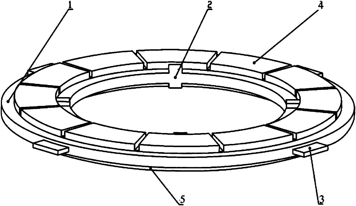
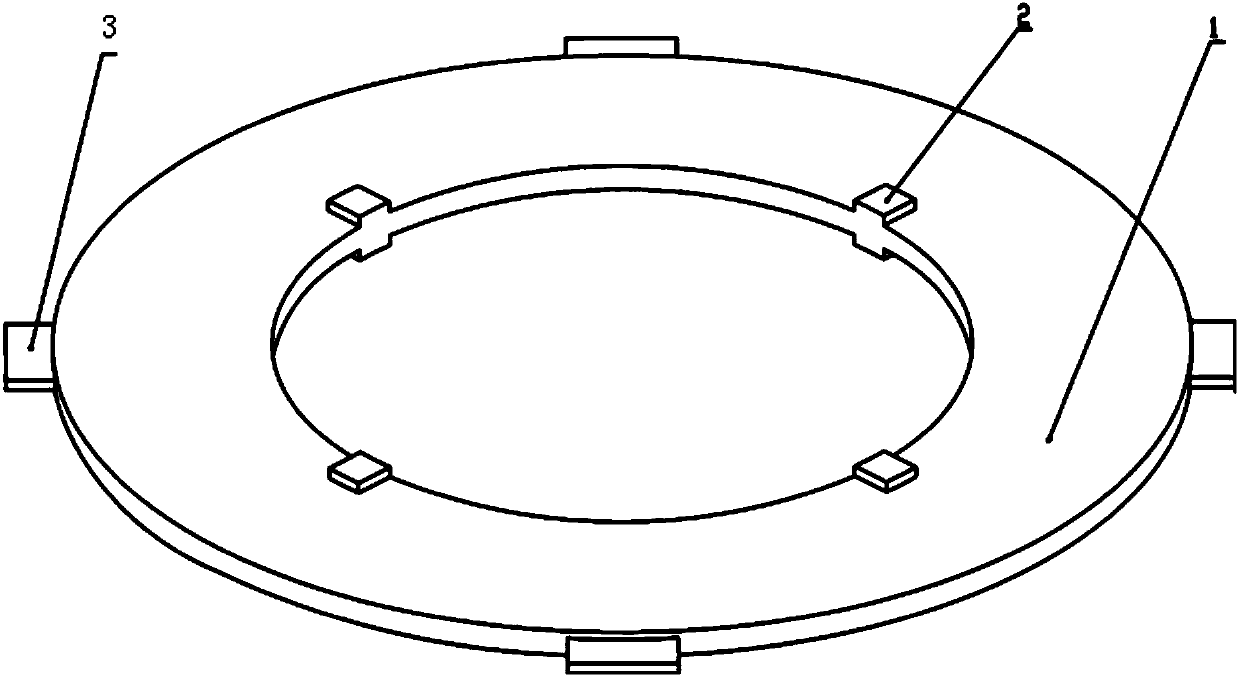
[0036] Specific implementation mode one: refer to Figure 1 to Figure 4 Describe this embodiment in detail. The stator base of the three-degree-of-freedom spherical rotor ultrasonic motor described in this embodiment includes a metal ring 1, four driving feet 2, ear-shaped fixed ends 3, an upper piezoelectric ceramic ring 4 and a lower piezoelectric ceramic ring. ceramic ring 5,

[0037] The four driving feet 2 are evenly embedded in the inner ring of the metal ring 1, and the four ear-shaped fixed ends 3 are evenly arranged on the outer ring of the metal ring 1.

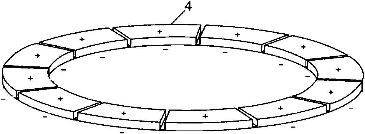
[0038] The upper piezoelectric ceramic ring 4 is located on the upper surface of the metal ring 1. The upper piezoelectric ceramic ring 4 is equally divided into twelve upper piezoelectric ceramic partitions, and there is a gap between two adjacent piezoelectric ceramic partitions. A silver-plated layer is provided, and the twelve upper-layer piezoelectric ceramic partitions are all polarized along the thickness di...

specific Embodiment approach 2

[0044]Embodiment 2: This embodiment is to further explain the stator base of the three-degree-of-freedom spherical rotor ultrasonic motor described in Embodiment 1. In this embodiment, each upper piezoelectric ceramic partition and the corresponding lower piezoelectric ceramic partition The spatial phase difference of 15°.

specific Embodiment approach 3

[0045] Embodiment 3: This embodiment is to further explain the three-degree-of-freedom spherical rotor ultrasonic motor stator base described in Embodiment 1. In this embodiment, the straight line formed from the ear-shaped fixed end 3 to the center of the circle and the adjacent drive The included angle between the straight line formed by foot 2 and the center of the circle is 45°.


PUM


Abstract

The invention discloses a three-degree-of-freedom spherical rotor ultrasonic motor stator base and an excitation method thereof, relates to the technical field of piezoelectric ultrasonic motors and aims to solve the problems of fewer driving feet, insufficient driving capability, complicated structure and difficulty in realizing miniaturization of an existing multi-degree-of-freedom rotational ultrasonic motor. Four driving feet are uniformly embedded into an inner ring of a metal ring, an upper piezoelectric ceramic ring and a lower piezoelectric ceramic ring are positioned on the upper surface and the lower surface of the metal ring, the upper piezoelectric ceramic ring is equally divided into twelve upper piezoelectric ceramic partitions, a gap is reserved between every two adjacent piezoelectric ceramic partitions, a silver coating is arranged at each gap, the lower piezoelectric ceramic ring is virtually and equally divided into twelve lower piezoelectric ceramic partitions, polarization directions in the upper piezoelectric ceramic ring are the same, polarization directions in the lower piezoelectric ceramic ring are the same, and the polarization directions between the upper piezoelectric ceramic ring and the lower piezoelectric ceramic ring are opposite. The base is used for an elliptical driving track of a driving rotor rotating around x, y and z axes.

Description

technical field [0001] The invention relates to a three-degree-of-freedom spherical rotor ultrasonic motor stator base body. It belongs to the technical field of piezoelectric ultrasonic motors. Background technique [0002] Piezoelectric ultrasonic motor is a kind of piezoelectric ultrasonic motor that uses the inverse piezoelectric effect of piezoelectric ceramics to excite vibration in the ultrasonic frequency range in the elastic body, and forms a particle motion with a specific trajectory at a specific point or area on the surface of the elastic body, and then passes through the stator, The frictional coupling between the rotors converts the microscopic motion of the particle into the macroscopic motion of the rotor, which has the advantages of low speed and high torque, no need for a speed change mechanism, no electromagnetic interference, fast response, and self-locking when power is off. [0003] However, the existing multi-degree-of-freedom rotary ultrasonic motors...

Claims


Application Information

Patent Timeline
Patent Type & Authority Applications(China)
IPC IPC(8): H02N2/14H02N2/10
Inventor 石胜君黄郅博刘英想刘军考陈维山
Owner HARBIN INST OF TECH
Why Eureka
Try Eureka