
Channel detection method and channel detection device

A channel detection and channel technology, which is applied in the field of communication, can solve the problems of long channel detection time and increased delay, and achieve the effects of reducing delay, improving system performance, and improving transmission efficiency

Active Publication Date: 2020-12-22
YULONG COMPUTER TELECOMM SCI (SHENZHEN) CO LTD
View PDF5 Cites 0 Cited by
  • Summary
  • Abstract
  • Description
  • Claims
  • Application Information

AI Technical Summary

Problems solved by technology

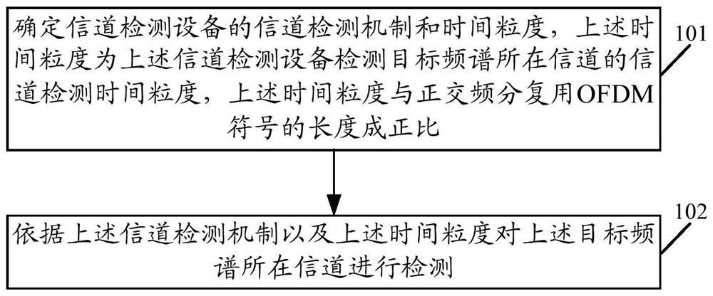
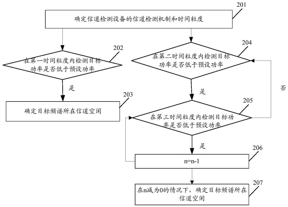
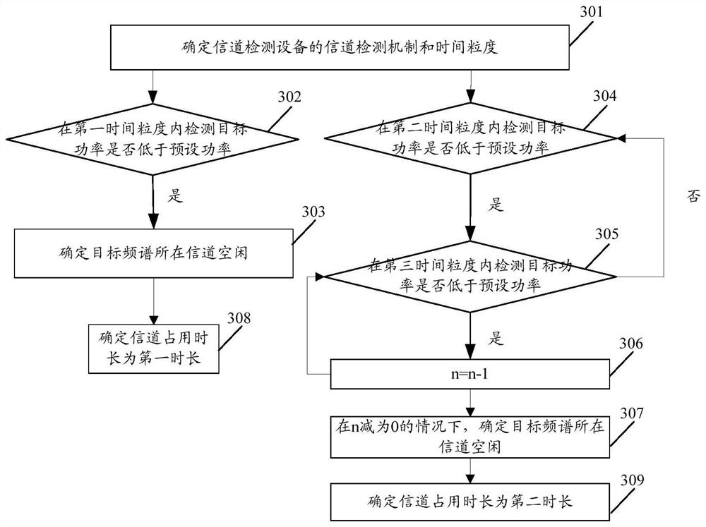
[0004] The embodiment of the present invention provides a channel detection method and channel detection equipment, which solves the problem of increased delay caused by a large channel detection time in NR technology, and proposes a channel detection time and channel detection time with a smaller granularity. Occupy time to reduce delay, improve transmission efficiency, and improve system performance

Method used


Image

  • Channel detection method and channel detection device
  • Channel detection method and channel detection device
  • Channel detection method and channel detection device

Examples


Embodiment Construction

[0059] In order to make the purpose, technical solution and advantages of the present invention clearer, the present invention will be further described in detail below in conjunction with the accompanying drawings. Apparently, the described embodiments are some, but not all, embodiments of the present invention. It is to be noted that the detailed description set forth in conjunction with the accompanying drawings is intended as a description of various configurations and is not intended to represent the only configurations in which the concepts described herein may be practiced. The device embodiments and method embodiments described herein will be described in the following detailed description, and various blocks, modules, units, components, circuits, steps, processes, algorithms, etc. (collectively referred to as "Elements") to be shown. These elements may be implemented using electronic hardware, computer software or any combination thereof. Whether these elements are ...


PUM


Abstract

The embodiment of the invention discloses a channel detection method and a channel detection device. The channel detection method can comprise the following steps: determining the channel detection mechanism and time granularity of the channel detection device, wherein the time granularity is a channel detection time granularity of a channel where a target frequency spectrum of the channel detection device is located, and the time granularity is in direct proportion to the length of an orthogonal frequency division multiplexing OFDM symbol; and detecting the channel where the target frequencyspectrum is located according to the channel detection mechanism and the time granularity. By adoption of the embodiment of the invention, the channel detection is achieved with smaller time granularity, the delay can be shortened, the transmission efficiency is improved, and the performance of the system is improved.

Description

technical field [0001] The invention relates to the technical field of communications, in particular to a channel detection method and channel detection equipment. Background technique [0002] In the long term evolution (Long Term Evolution, LTE) assisted case, the unlicensed spectrum is accessed based on the LTE structure, the subcarrier spacing is 15 KHz, and each subframe is 1 ms, which is divided into 14 symbols. Under such a structure, for the oneshot channel detection mechanism, that is, the downlink channel detection mechanism for sending Discovery Reference Signal (DRS) does not include Physical Downlink Shared Channel (PDSCH) or uplink The type 2 mechanism is to detect that the channel is idle within 25us, which means that the channel is idle, and 25us is divided into 16us+9us. Under this mechanism, if it is downlink channel detection, the downlink channel occupancy time cannot exceed 1ms. If the downlink channel detection is successful, the downlink channel has b...

Claims


Application Information

Patent Timeline
Patent Type & Authority Patents(China)
IPC IPC(8): H04B17/382H04L27/26
Inventor 李明菊张云飞
Owner YULONG COMPUTER TELECOMM SCI (SHENZHEN) CO LTD
Learn More