Light guide arm arranged on laser beauty therapy apparatus

A technology of a treatment machine and a light guide arm, which is applied in the field of light guide arms, can solve the problems of difficulty in controlling the tightness, difficulty, and loose joints, etc., and achieves the effect of improving the use performance and adjusting the flexibility and change.

Pending Publication Date: 2018-01-23
JINGYU LASER TECH CHONGQING
View PDF7 Cites 0 Cited by
  • Summary
  • Abstract
  • Description
  • Claims
  • Application Information

AI Technical Summary

Problems solved by technology

[0002] Laser beauty treatment machine is a common equipment for freckle removal and beauty treatment. The laser head on the device is installed on the light guide arm. Since the position of the laser head needs to be changed frequently during treatment to meet the needs of the operation, most of the guide The optical arm is made of several connecting rods (or metal struts) hinged to each other, making a "joint" connecting rod with multiple degrees of freedom, and in order to prevent the "joint" of the laser head from loosening suddenly when the laser head is fixed in position, affecting In surgery, the "joint" points that are usually hinged are damped hinged, that is, the joint flexibility has a certain limit
The tightness of the hinge of the existing light guide arm is difficult to control and cannot be adjusted. It is difficult to adjust the tightness of the hinge according to needs, and it is difficult to adjust and repair when the hinge is loose due to wear and other reasons after long-term use. The personnel will hold the laser head with their hands, but the loosening of the joints of the light guide arm will still affect the operation

Method used


Image

  • Light guide arm arranged on laser beauty therapy apparatus
  • Light guide arm arranged on laser beauty therapy apparatus
  • Light guide arm arranged on laser beauty therapy apparatus

Examples


Embodiment Construction

[0017] The implementation of the present invention will be illustrated by specific specific examples below, and those skilled in the art can easily understand other advantages and effects of the present invention from the contents disclosed in this specification.

[0018] Below in conjunction with accompanying drawing and embodiment the present invention will be further described:

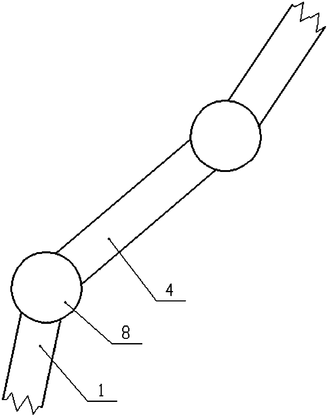
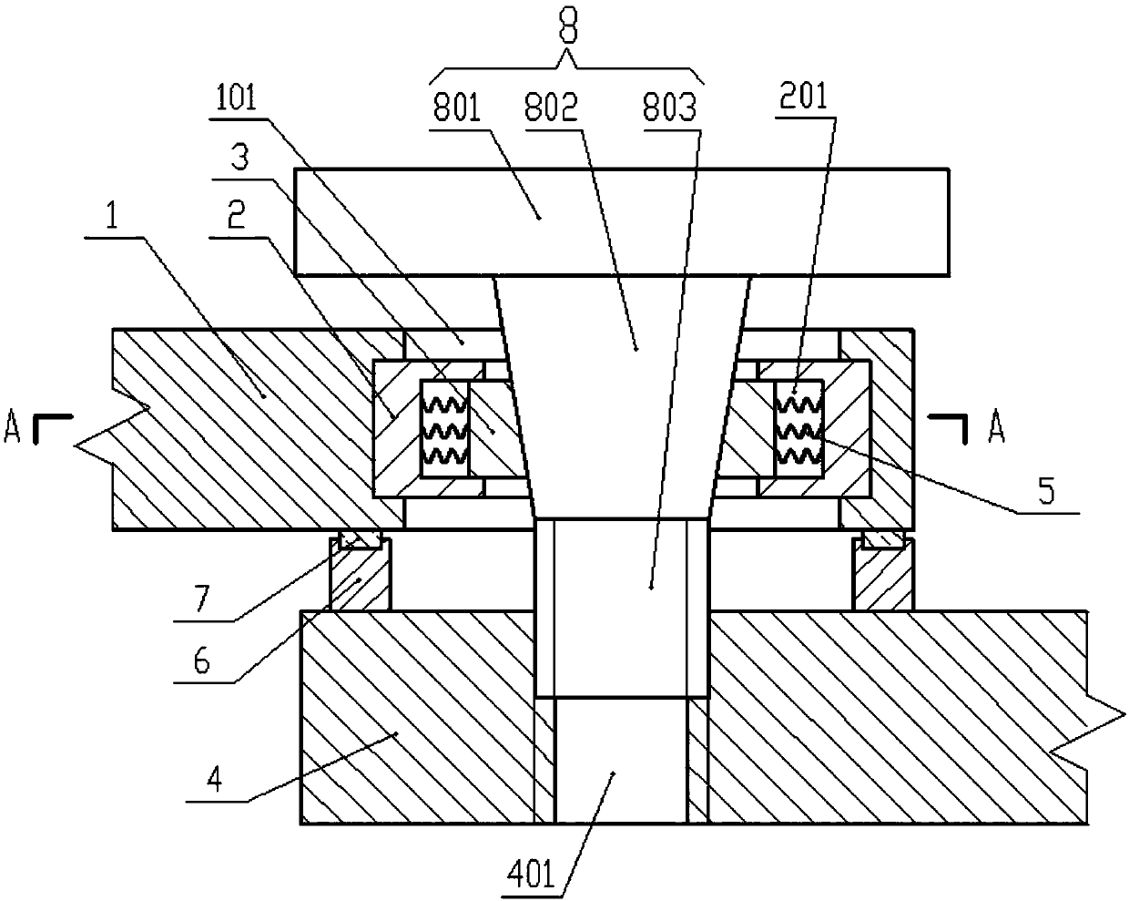
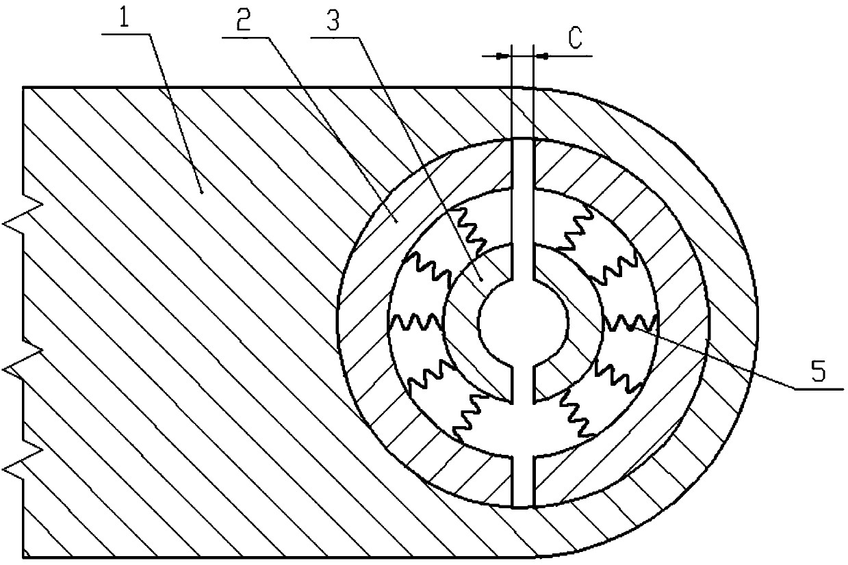
[0019] Such as figure 1 - As shown in -3, a light guide arm on a laser cosmetic treatment machine includes several connecting rods hinged in turn; the end of the first connecting rod 1 in the two connecting rods hinged to each other is provided with a through hole 101, and the through hole 101 is provided at the end of the connecting rod The inner wall of the hole 101 is provided with a circle of [-shaped grooves in cross section.

[0020] It also includes two first sliders 2 and two second sliders 3 coaxially arranged in the shape of tiles, and the two first sliders 2 and the two second sliders 3...


PUM


Abstract

The invention discloses a light guide arm on a laser beauty therapy apparatus. The light guide arm comprises a plurality of connecting rods which are hinged in sequence. A through hole is formed in the end of a first connecting rod among two mutually hinged two connecting rods. A circle of groove, with an I-shaped cross section, is formed in the inner wall of the through hole. The light guide armfurther comprises two first sliding blocks and two second sliding blocks, wherein the first and second sliding blocks are arranged in a tile shape and are coaxially arranged. The two first sliding blocks and the two second sliding blocks are oppositely arranged to form an incomplete circular ring. A threaded through hole is formed in the end face of the hinged part of a second connecting rod. Theend surface of the threaded through hole, opposite to the first connecting rod, is provided with a cushion ring. The end surface of the cushion ring, opposite to the first connecting rod, is fixedly provided with a graphite ring. The threaded section of an adjusting bolt is screwed into the threaded through hole. The surface of one side of the first connecting rod, right facing the second connecting rod, is in smooth connection with the end surface of the graphite ring. A conical shaft is matched with the inner walls of the second sliding blocks so as to compress a spring. According to the invention, the joint flexibility of the light guide arm can be flexibly adjusted.

Description

technical field [0001] The invention belongs to the technical field of laser treatment machines, in particular to a light guide arm on a laser cosmetic treatment machine. Background technique [0002] Laser beauty treatment machine is a common equipment for freckle removal and beauty treatment. The laser head on the device is installed on the light guide arm. Since the position of the laser head needs to be changed frequently during treatment to meet the needs of the operation, most of the guide The optical arm is made of several connecting rods (or metal struts) hinged to each other, making a "joint" connecting rod with multiple degrees of freedom, and in order to prevent the "joint" of the laser head from loosening suddenly when the laser head is fixed in position, affecting In surgery, the "joint" points usually hinged are damped hinges, that is, the flexibility of the joints has a certain limit. The tightness of the hinge of the existing light guide arm is difficult to ...

Claims


Application Information

Patent Timeline
Patent Type & Authority Applications(China)
IPC IPC(8): A61N5/067
Inventor 廖政郑真平梅国辉韦庆强
Owner JINGYU LASER TECH CHONGQING
Why Eureka
Try Eureka