Efficient flange mold structure for flange rapid forming and casting method

A flange and fast technology, applied in casting equipment, casting molding equipment, casting molds, etc., can solve the problems of low molding efficiency, inability to adjust processing efficiency and output, and inability to adjust condensation molding efficiency, etc., to achieve the effect of flexible and convenient use

Inactive Publication Date: 2020-07-10
WUHU JINMAO FLUID TECH CO LTD
View PDF5 Cites 0 Cited by
  • Summary
  • Abstract
  • Description
  • Claims
  • Application Information

AI Technical Summary

Problems solved by technology

[0002] At present, when processing flange workpieces by casting, the sand boxes used are often traditional sand box structures. Although they can meet the needs of use to a certain extent, on the one hand, the flexibility of casting processing is poor, and the processing efficiency cannot be flexibly adjusted according to the needs of use. and output; on the other hand, in the process of processing, it is impossible to adjust the condensation molding efficiency, and it is also impossible to monitor and adjust the temperature change in the condensation process, which leads to low molding efficiency and is also very easy to die due to uneven cooling temperature distribution. Causes internal stress concentration of the workpiece, and in severe cases, the structural strength of the flange workpiece is poor, internal cracks, etc. seriously affect the quality of the flange due to stress concentration.
[0003] At the same time, the current sand box lacks the ability to effectively modulate the metal crystal phase structure during the cooling and forming process, which further affects the structure of the casting flange workpiece

Method used


Image

  • Efficient flange mold structure for flange rapid forming and casting method
  • Efficient flange mold structure for flange rapid forming and casting method

Examples


Embodiment Construction

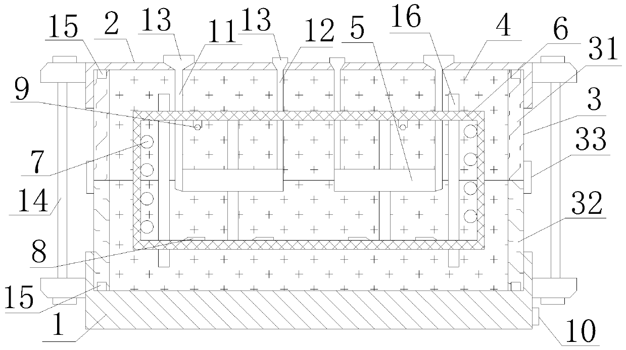
[0020] Such as figure 1 As shown, a high-efficiency flange mold structure for rapid prototyping of flanges includes a bearing base 1, a sealing end cover 2, a molding box 3, molding sand 4, a molding sand core 5, a bearing keel 6, a heat exchange tube 7, and an electromagnet 8 , the temperature sensor 9 and the drive circuit 10, the carrying base 1 and the sealing cover 2 both have a cross-section in the shape of a "凵"-shaped groove structure, the carrying base 1 and the sealing end cover 2 are connected by a forming box 3, and the forming box 3 It is a rectangular closed frame structure coaxially distributed with the bearing base 1 and the sealing end cover 2, and forms a closed cavity structure together with the bearing base 1 and the sealing end cover 2. The bearing keel 6 is embedded in the forming box 3, and is A frame structure coaxially distributed with the forming box 3, 2-8 forming sand cores 5 in total, embedded in the forming box 3 through the bearing keel 6, and di...


PUM


Abstract

The invention discloses an efficient flange mold structure for flange rapid forming. The efficient flange mold structure for flange rapid forming comprises a bearing base, a sealing end cover, a forming box body, molding sand, forming sand cores, a bearing keel, a heat exchange pipe, an electromagnet, a temperature sensor and a driving circuit, the bearing base and the sealing end cover are connected through the forming box body, the bearing keel is embedded in the forming box body, the forming sand cores are embedded in the forming box body through the bearing keel, the molding sand is located in the forming box body and coats the forming sand cores and the bearing keel, and a runner and an exhaust passage are arranged at each of the positions, corresponding to the forming sand cores, ofthe molding sand. The casting method based on the efficient flange mold structure for flange rapid forming comprises two steps of equipment assembly and casting operation. According to the efficient flange mold structure for flange rapid forming and the casting method, on one hand, the requirement for casting machining of one or more flange workpieces can be flexibly met according to use requirements; and on the other hand, the defects of poor metal material structural strength and sand holes, cracks and the like of a flange structure caused by stress concentration inside the flange can be effectively eliminated.

Description

technical field [0001] The invention relates to a flange rapid prototyping high-efficiency flange mold structure and a casting method, belonging to the casting process technology. Background technique [0002] At present, when processing flange workpieces by casting, the sand boxes used are often traditional sand box structures. Although they can meet the needs of use to a certain extent, on the one hand, the flexibility of casting processing is poor, and the processing efficiency cannot be flexibly adjusted according to the needs of use. and output; on the other hand, in the process of processing, it is impossible to adjust the condensation molding efficiency, and it is also impossible to monitor and adjust the temperature change in the condensation process, which leads to low molding efficiency and is also very easy to die due to uneven cooling temperature distribution. The internal stress concentration of the workpiece is caused, and in severe cases, even the structural s...

Claims


Application Information

Patent Timeline
Patent Type & Authority Applications(China)
IPC IPC(8): B22C9/02B22C9/24B22D27/02B22D27/04B22D2/00B22C9/20B22C21/02B22C9/10
CPCB22C9/02B22C9/108B22C9/20B22C9/24B22C21/02B22D2/006B22D27/02B22D27/04
Inventor 孙述全孙雄
Owner WUHU JINMAO FLUID TECH CO LTD
Why Eureka
Try Eureka