Air sealing body
A gas sealing and air chamber technology, applied in the direction of preventing mechanical damage, containers, transportation and packaging, etc., can solve the problems of accelerated air leakage, easy to be torn, etc., and achieve the effect of maintaining the sealing effect
- Summary
- Abstract
- Description
- Claims
- Application Information
AI Technical Summary
Problems solved by technology
Method used
Image

Examples
no. 1 example
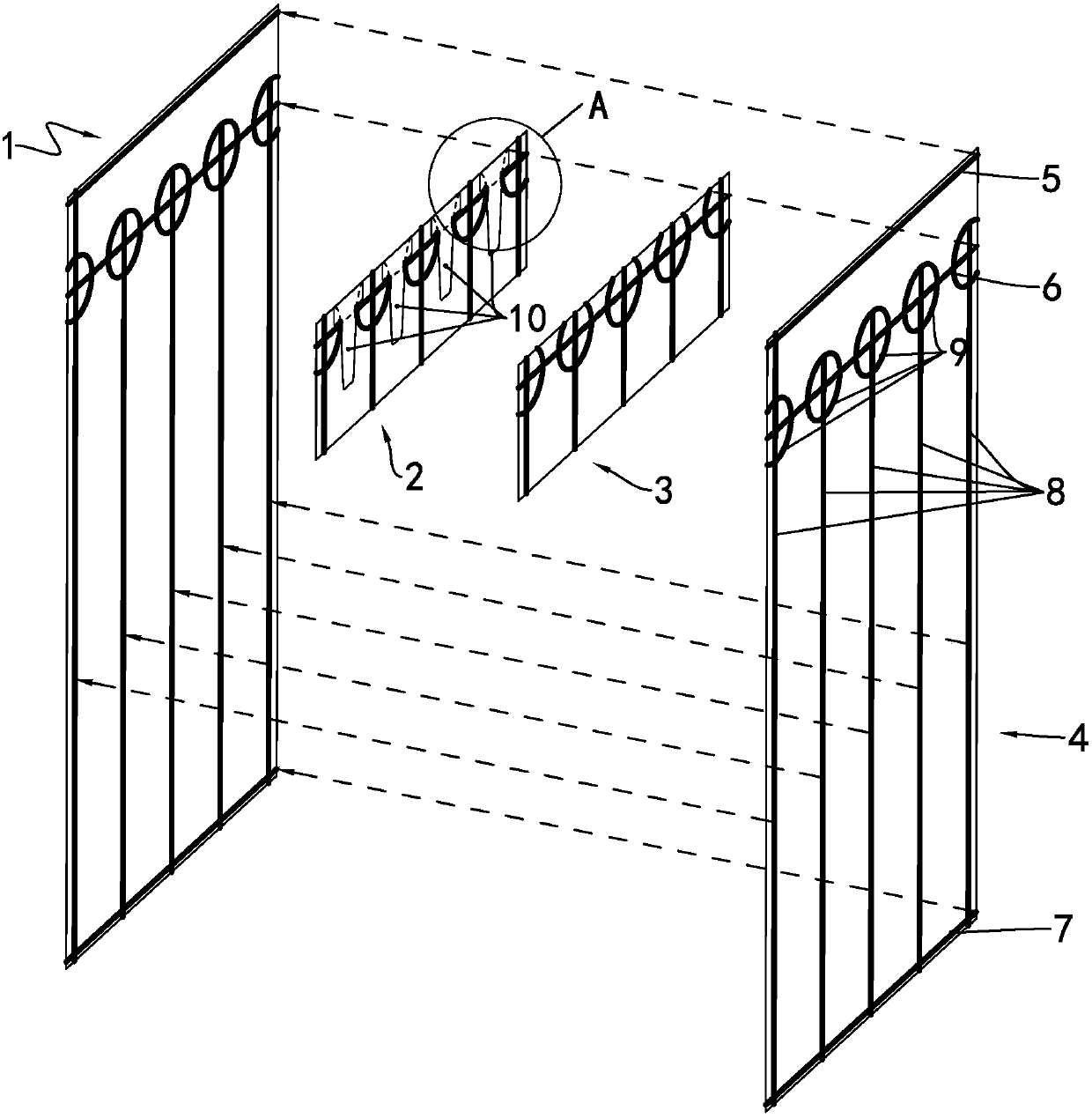
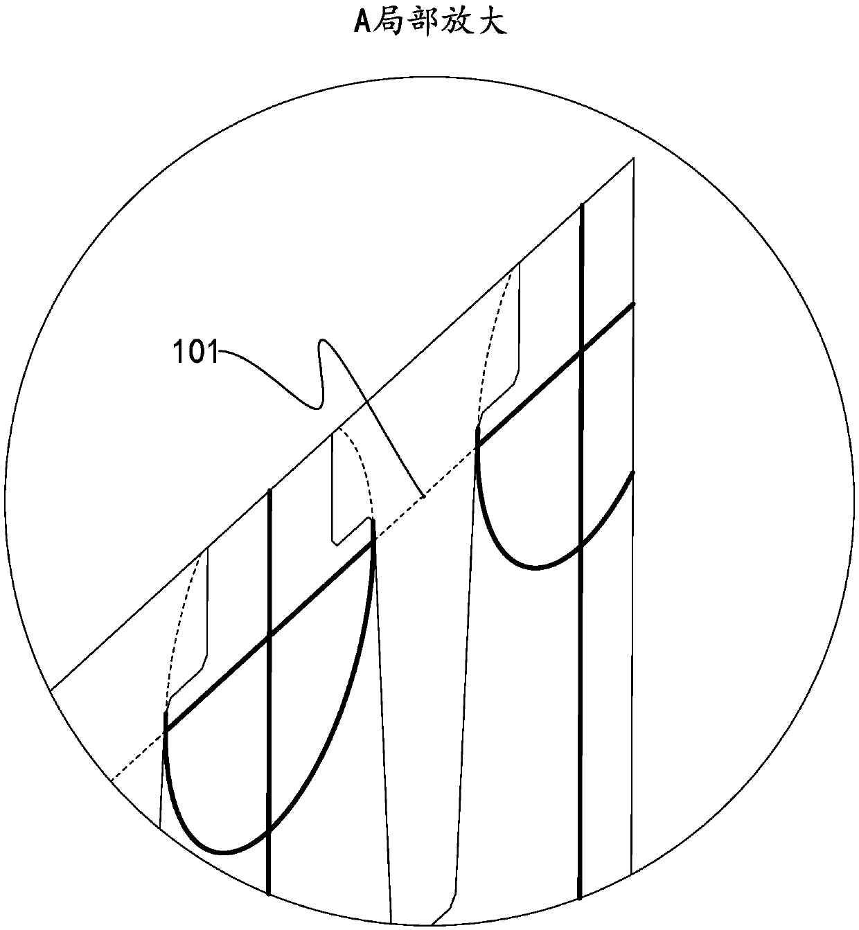
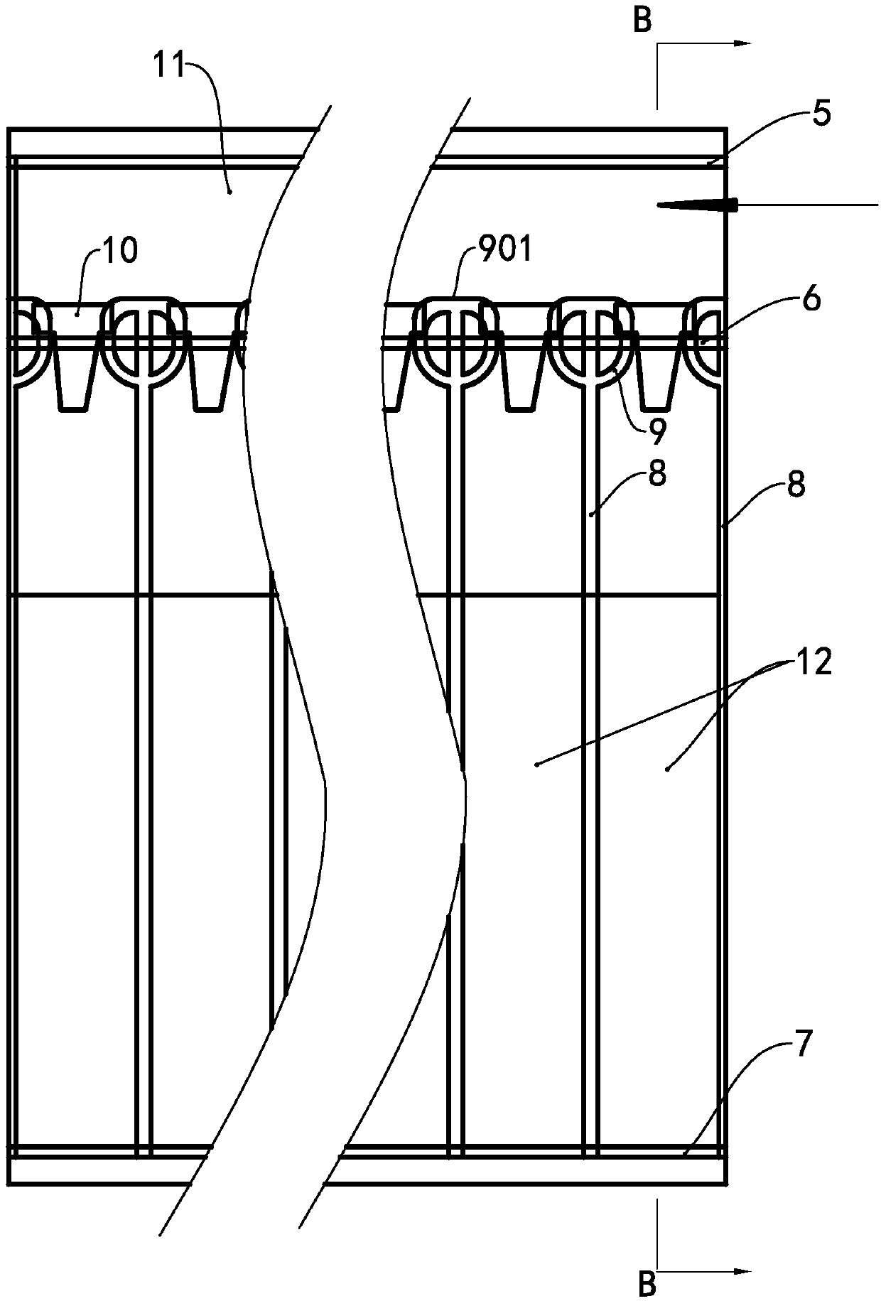
[0029] The main improvement of the present invention is on the one hand the shape of the isolation heat-sealing line and its positional relationship with the T-shaped heat-resistant block, and on the other hand the inner film material, so the difference in the first aspect can also be compared image 3 inferred. The following mainly describes the differences in detail, and those skilled in the art can fully implement the present embodiment according to the content introduced in the prior art. see Figure 5 , by the upper heat-sealing line 5, the middle heat-sealing line 6 and Figure 5 In the inflation channel 11 surrounded by the leftmost longitudinal side seal line in the center, there are the top of the T-shaped heat-resistant block and the top of the isolation heat-sealing line, so these two tops are also above the heat-sealing line 6 in the middle.
[0030] see Figure 6 , the isolation heat-sealing line 9 is on the upper part of the longitudinal heat-sealing line 8, a...
no. 2 example
[0035] Only the difference between this example and the first embodiment will be described below. This case is characterized by only one piece of intima, as in Figure 7 When the first step of heat sealing is shown, the T-shaped heat-resistant block 10 on the inner film should be on the surface facing the outer film 1.
Embodiment approach
[0037] The specific form of the gas sealing body of the present invention can be a flat pad as disclosed in CN1903678, or a U-shaped bag as disclosed in CN1903677A, or a C-shaped bag as disclosed in CN1903675A, or a J-shaped bag as disclosed in CN1903676A, or other suitable for being used. The special form of the appearance characteristics of the packaged goods, such as the shockproof sleeve disclosed in CN102107750A, these forms are all gas-tight bodies referred to in the present invention.
PUM
 Abstract
Description
Claims
Application Information
 - R&D
- Intellectual Property
- Life Sciences
- Materials
- Tech Scout
- Unparalleled Data Quality
- Higher Quality Content
- 60% Fewer Hallucinations
Browse by: Latest US Patents, China's latest patents, Technical Efficacy Thesaurus, Application Domain, Technology Topic, Popular Technical Reports.
© 2025 PatSnap. All rights reserved.Legal|Privacy policy|Modern Slavery Act Transparency Statement|Sitemap|About US| Contact US: help@patsnap.com