
Ultrasonic laser drilling device

An ultrasonic and drilling technology, which is applied in the direction of drilling equipment, earthwork drilling, drilling equipment and methods, etc., can solve the problem of not being able to drill through hard strata and rock formations, and achieve good results

Active Publication Date: 2018-01-23
CHINA WEAPON EQUIP RES INST
View PDF6 Cites 5 Cited by
  • Summary
  • Abstract
  • Description
  • Claims
  • Application Information

AI Technical Summary

Benefits of technology

This technology can use powerful pulsed light beams from an ultraviolet (UV) lamp or other source to break rocks into small pieces that are then removed with special tools like hammers for creating holes on top ground surfaces during construction work.

Problems solved by technology

The technical problem addressed by this patented study relates to improving the effectiveness and reliability of drill bits when excavating rocks underground due to increasing difficulty or difficulties encountered while drilling deeper holes. This can lead to increased costs associated with drills that have been developed over recent years without being able to effectively break up these difficult materials.

Method used


Image

  • Ultrasonic laser drilling device
  • Ultrasonic laser drilling device

Examples


Embodiment Construction

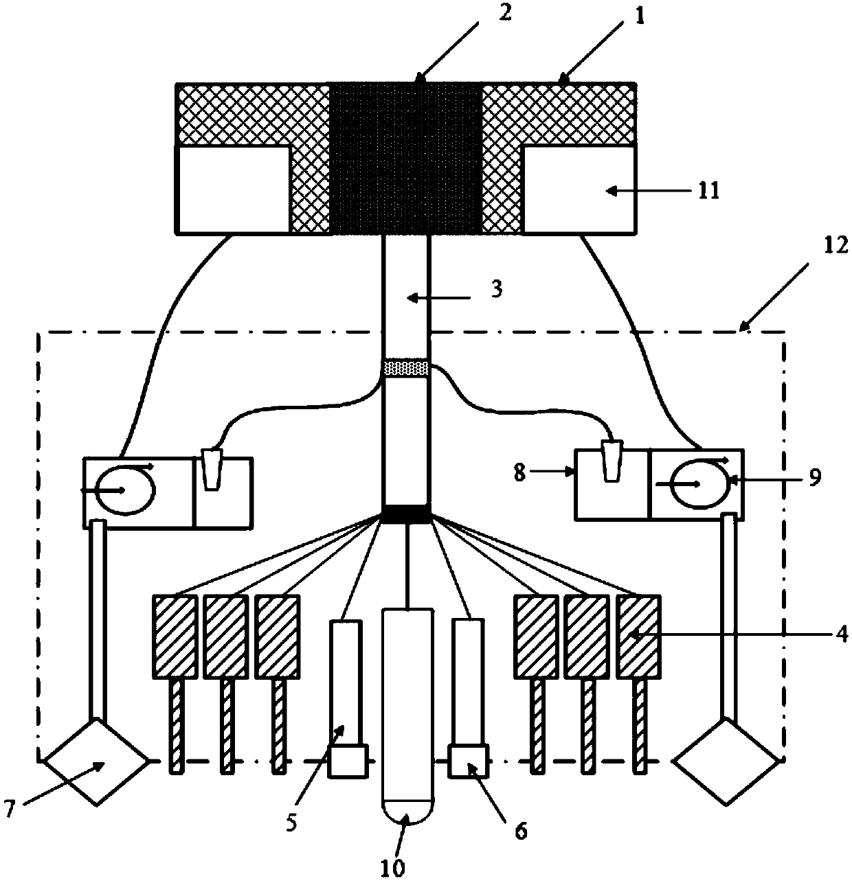
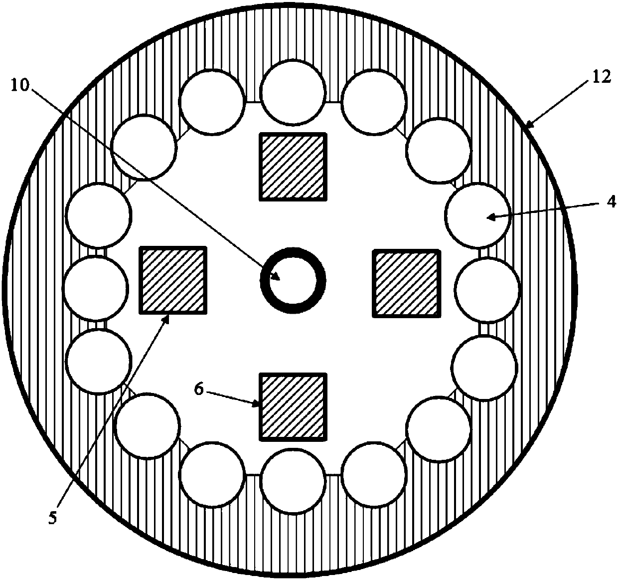
[0016] An ultrasonic laser drilling device is characterized in that it includes: a cooling unit 1, a control unit 2, a connecting pipe 3, a filter tank 11, a high-power pulsed laser array 4, an ultrasonic generator 5 and an ultrasonic focusing array 6, wherein the communicating pipe There are cables, high-strength water pipes and return pipes in the 3, and the cables in the connecting pipe 3 connect the control unit 2 with the high-power pulsed laser array 4, multiple ultrasonic generators 5, ultrasonic focusing array 6 and The air pump 9 is connected, and the high-strength water pipe in the connecting pipe 3 connects the cooling unit 1 with the cooling water circulation system of the high-power pulse laser array 4, the ultrasonic generator 5 and the ultrasonic focusing array 6, and the cooled water passes through the connecting pipe 3. The return water pipe returns to the cooling unit 1, the high-strength water pipe in the communication pipe 3 is also connected to the water st...


PUM

PropertyMeasurementUnit
Energy densityaaaaaaaaaa

Abstract

An ultrasonic laser drilling device is characterized in that the ultrasonic laser drilling device comprises a cooling unit (1), a control unit (2), a communicating pipe (3), a filter tank (11), a high-power pulsed laser array (4), a plurality of ultrasonic generators (5) and an ultrasonic focusing array (6). A cable, a high-strength water pipe and a water returning pipe are arranged in the communicating pipe (3); the cable in the communicating pipe (3) enables the control unit (2) to be connected with the high-power pulsed laser array (4), the multiple ultrasonic generators (5), the ultrasonicfocusing array (6) and air pumps (9) in a shell (12) on the lower portion; and the high-strength water pipe in the communicating pipe (3) enables the cooling unit (1) to be connected with a cooling water circulation system of the high-power pulsed laser array (4), the ultrasonic generators (5) and the ultrasonic focusing array (6). The high-power pulsed laser devices emit high-pulse energy, and the ultrasonic generators damage the rock structure through the focusing array, so that rock breaking drilling is achieved, and the effect is good.

Description


Claims


Application Information

Patent Timeline
Owner CHINA WEAPON EQUIP RES INST
Learn More