Mobile terminal

A mobile terminal and input terminal technology, applied in electric vehicles, electrical components, transportation and packaging, etc., can solve problems such as inability to work independently, affect the normal charging or use of mobile terminals, and affect user experience

Inactive Publication Date: 2018-01-23
深圳市东宇科技有限公司
View PDF6 Cites 2 Cited by
  • Summary
  • Abstract
  • Description
  • Claims
  • Application Information

AI Technical Summary

Problems solved by technology

[0002] At present, with the improvement of people's living standards and the development of science and technology, people have more and more functional requirements for mobile terminals. Therefore, the functions of mobile terminals are changing with each passing day and developing very rapidly. Traditional mobile terminals generally use wired charging. However, because the wired charging method requires users to carry charging cables and plugs with them, which affects user experience, wireless charging technology applied to mobile terminals has emerged as the times require
[0003] However, in the process of implementing the present invention, the inventor found that the prior art has the following technical problems: in the prior art, when a mobile terminal has both a wired charging function and a wireless charging function, the difference between the wired charging circuit and the wireless charging circuit Often there will be mutual interference or simultaneous work between the two, resulting in the two can not work independently, affecting the normal charging or use of the mobile terminal, therefore, can provide a way to ensure that the wired charging circuit and the wireless charging circuit work independently and do not Mobile terminals that interfere with each other are particularly important

Method used

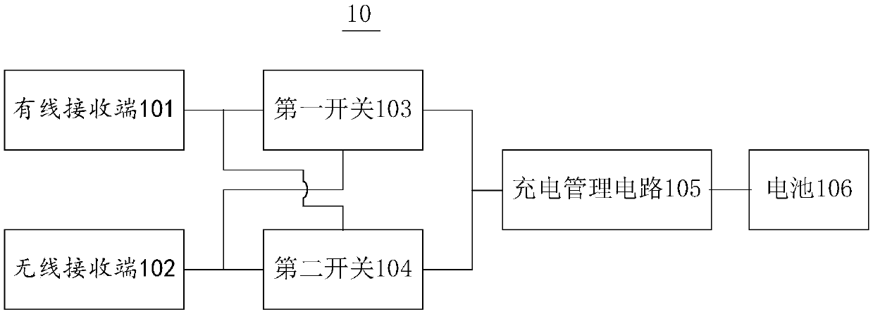
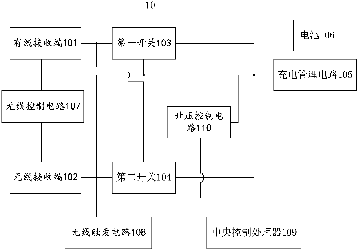
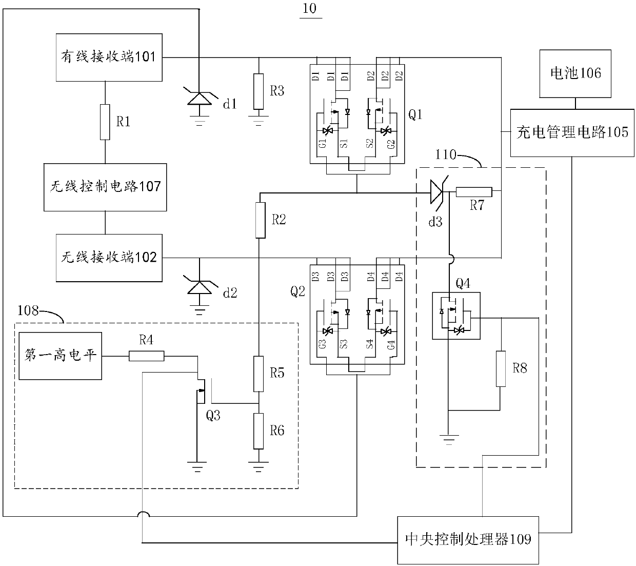

Image

  • Mobile terminal
  • Mobile terminal
  • Mobile terminal

Examples


Embodiment Construction

[0035] In order to facilitate the understanding of the present invention, the present invention will be described in more detail below in conjunction with the accompanying drawings and specific embodiments. It should be noted that when an element is said to be "fixed" to another element, it may be directly on the other element, or there may be one or more intervening elements therebetween. When an element is referred to as being "connected to" another element, it can be directly connected to the other element or one or more intervening elements may be present therebetween. The terms "vertical", "horizontal", "left", "right" and similar expressions are used in this specification for the purpose of description only.

[0036] Unless otherwise defined, all technical and scientific terms used in this specification have the same meaning as commonly understood by one of ordinary skill in the technical field of the invention. The terminology used in the description of the present inv...


PUM


Abstract

The embodiment of the invention relates to the field of a mobile terminal, and particularly relates to a mobile terminal. The mobile terminal comprises a wired receiving end, a wireless receiving end,a first switch, a second switch, a charge management circuit and a battery, wherein the wired receiving end is connected with the charge management circuit by the first switch; the wireless receivingend is connected with the charge management circuit by the second switch; the battery is connected with the charge management circuit; the wireless receiving end controls on-off of the first switch;and the wired receiving end controls on-off of the second switch. In the mode, according to the embodiment of the invention, at most one charging circuit in a wired charging circuit and a wireless charging circuit can be in a working state of charging, the wired charging circuit and the wireless charging circuit are guaranteed to independently work, a case that the wired charging circuit and the wireless charging circuit simultaneously work, interfere each other and damage the mobile terminal is avoided, and the charging process is safer and more reliable.

Description

technical field [0001] The embodiments of the present invention relate to the field of mobile terminals, and in particular, to a mobile terminal. Background technique [0002] At present, with the improvement of people's living standards and the development of science and technology, people have more and more functional requirements for mobile terminals. Therefore, the functions of mobile terminals are changing with each passing day and developing very rapidly. Traditional mobile terminals generally use wired charging. However, because the wired charging method requires users to carry charging cables and plugs with them, which affects user experience, wireless charging technology applied to mobile terminals has emerged as the times require. [0003] However, in the process of implementing the present invention, the inventor found that the prior art has the following technical problems: in the prior art, when a mobile terminal has both a wired charging function and a wireless...

Claims


Application Information

Patent Timeline
Patent Type & Authority Applications(China)
IPC IPC(8): H02J7/00H02J50/00
Inventor 万华付
Owner 深圳市东宇科技有限公司
Why Eureka
Try Eureka