Electric automobile regenerative brake control method based on multi-constraint conditions

A technology of electric vehicles and regenerative braking force, which is applied in the direction of electric vehicles, electric braking systems, vehicle components, etc., and can solve the problems of not taking regenerative braking into consideration, threatening safety, shortening lifespan, etc.

Inactive Publication Date: 2015-11-11
UNIV OF ELECTRONIC SCI & TECH OF CHINA
View PDF6 Cites 19 Cited by
  • Summary
  • Abstract
  • Description
  • Claims
  • Application Information

AI Technical Summary

Problems solved by technology

[0004] However, the above existing methods have not considered an important object in regenerative braking - the battery
As an energy storage device,

Method used


Image

  • Electric automobile regenerative brake control method based on multi-constraint conditions
  • Electric automobile regenerative brake control method based on multi-constraint conditions
  • Electric automobile regenerative brake control method based on multi-constraint conditions

Examples


Embodiment

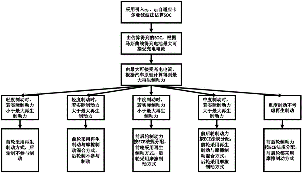
[0078] figure 1 It is a flow chart of the electric vehicle regenerative braking control method based on multiple constraint conditions in the present invention.

[0079] In this embodiment, the present invention is based on the electric vehicle regenerative braking control method under multiple constraint conditions, mainly including two steps: calculating regenerative braking force and regenerative braking control based on multiple constraint conditions, combined below figure 1 The two steps are described in detail as follows:

[0080] S1. Calculate the regenerative braking force according to the charging current of the battery

[0081] S1.1. Estimating the state of charge SOC of the electric vehicle battery

[0082] S1.1.1. Collect the current at the battery input terminal through the current sensor, then collect the temperature of the braking system through the temperature sensor, and perform fitting training through MATLAB to obtain the influence factor η of the temperat...

example

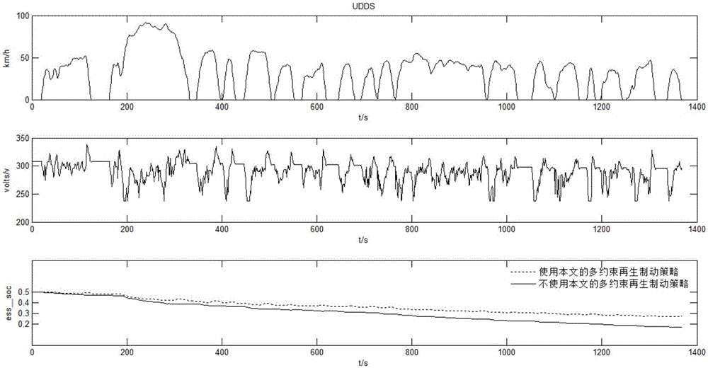
[0136] Establish a pure electric vehicle model in ADVISOR, and verify it by establishing actual road conditions, and the actual road conditions choose 4 common working conditions in ADVISOR: New York City Working Condition NYCC, Urban Road Cycle Working Condition UDDS formulated by the US Environmental Protection Agency EPA , EUDC_LOW for European urban low-speed conditions, and HWFET for highway conditions.

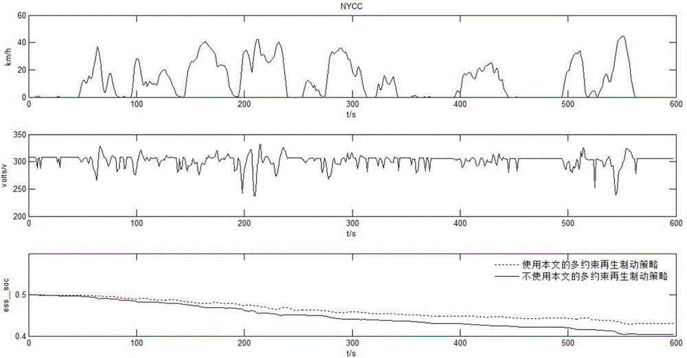
[0137] (1), New York city working condition NYCC

[0138] Such as figure 2 As shown, the first picture in the figure shows the vehicle speed under the NYCC working condition, the second picture shows the battery charging voltage under this working condition, and the dotted line in the third picture shows the SOC after using the regenerative braking strategy described in the present invention The change trend, the solid line in the third figure indicates the SOC change trend after using the regenerative braking strategy in the ADVISOR software. It can be seen from the ...


PUM


Abstract

The invention discloses an electric automobile regenerative brake control method based on multi-constraint conditions. Firstly, the optimal charging current of a battery is estimated according to the state of charge (SOC) of the battery, the actual charging current of the battery is made to approach the maximum charging current curve of the battery through a current control algorithm, the maximum regenerative braking force is calculated according to the maximum charging current, and the charging efficiency is improved; secondly, regenerative braking is divided into three grades according to the amplitude of braking strength, the constraint conditions of ECE regulation on moment distribution are analyzed, the regenerative braking force is allocated on the basis of the ECE regulation according to the influences of braking force strength and a ground adhesive force coefficient on an allocation strategy, braking safety is guaranteed, influences of moment allocation, the SOC of the battery, charging of the battery and other factors on the braking process are reduced, and the energy recycling efficiency is improved to a large extent.

Description

technical field [0001] The invention belongs to the technical field of electric vehicles, and more specifically relates to a regenerative braking control method for electric vehicles based on multiple constraint conditions. Background technique [0002] As energy issues have become the focus of the world, traditional fuel vehicles are gradually being replaced by electric vehicles, and governments of various countries have introduced relevant policies to support pure electric vehicles. One of the core issues affecting the development of pure electric vehicles is how to make them run longer distances on a single charge, so the regenerative braking control strategy is particularly important. [0003] In the prior art, regenerative braking control strategies include: using a regenerative braking control method based on the target slip rate. During the control process, different control strategies are adopted according to the vehicle slip rate, which can improve the braking perfo...

Claims


Application Information

Patent Timeline
IPC IPC(8): B60L7/10
Inventor 郑宏李方方杨园园魏旻曹继申
Owner UNIV OF ELECTRONIC SCI & TECH OF CHINA
Why Eureka
Try Eureka