Charging control device, charging control method and wireless power receiving device equipped with same

a charging control and wireless power technology, applied in the direction of charging data exchange, exchanging data chargers, transportation and packaging, etc., can solve the problems of inefficiency of charging control, damage to the object to be charged, damage to the receiving terminal, etc., to reduce the charging time, improve charging efficiency, secure the effect of charging safety

Active Publication Date: 2016-08-04
LG INNOTEK CO LTD
View PDF0 Cites 21 Cited by
  • Summary
  • Abstract
  • Description
  • Claims
  • Application Information

AI Technical Summary

Benefits of technology

[0015]According to the embodiment, over voltage supplied to the load can be blocked to protect the load so that the charging safety can be secured.
[0016]According to the embodiment, since the over voltage is converted into charging voltage while the over voltage is being supplied, the charging voltage can be continuously supplied to the load even if the over voltage is blocked, so that the charging efficiency can be improved at the load and the charging time can be shortened.
[0017]The embodiment includes only the switch and the capacitor and the switch can be controlled by using voltage of the capacitor in order to block voltage supplied to the load, so that the configuration can be simplified and the additional cost may not be caused.
[0018]Meanwhile, other various effects will be directly or implicitly described below in the detailed description of the embodiments.

Problems solved by technology

Meanwhile, if the wireless power is indefinitely supplied to the receiving terminal, the receiving terminal may be damaged.
Especially, an object to be charged may be damaged due to over voltage.
However, according to the above patent document, a power generating unit, which has a complex structure to generate a predetermined low-voltage power supply, is necessary so that the charging control is inefficient.

Method used


Image

  • Charging control device, charging control method and wireless power receiving device equipped with same
  • Charging control device, charging control method and wireless power receiving device equipped with same
  • Charging control device, charging control method and wireless power receiving device equipped with same

Examples


first embodiment

[0087]FIG. 5 is a block diagram showing a wireless power transmission system according to a

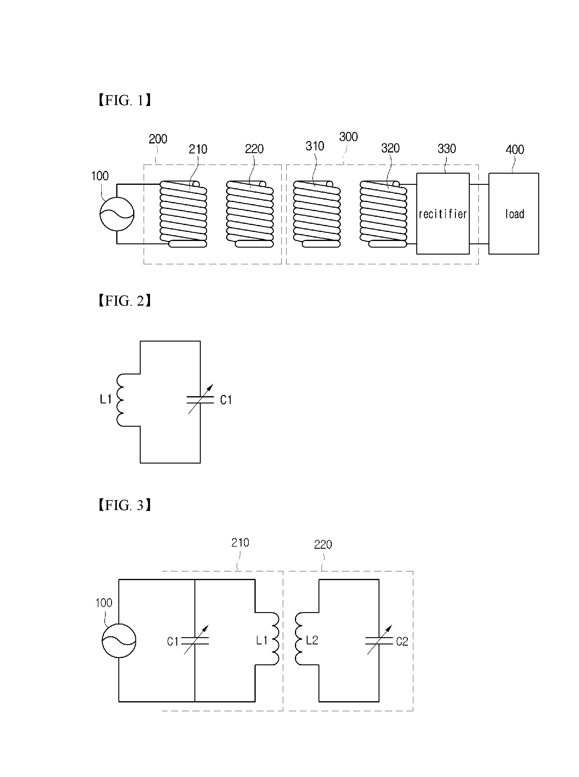
[0088]Referring to FIG. 5, the wireless power transmission system according to the first embodiment may include a power source 100, a wireless power transmitter 200, a wireless power receiver 300 and a load 400.

[0089]Since the power source 100 and the load 400 have been described above in detail, they will not be further described below.

[0090]According to the first embodiment, the wireless power transmitter 200 and the wireless power receiver 300 may exchange information with each other through the in-band communication scheme. The in-band communication scheme according to the first embodiment may not require a separate transmission module or a separate reception module for data communication as well as a separate communication frequency used for communication in the communication modules. Since the transmission module and the reception module are not necessary, there is no need to define the ...

second embodiment

[0193]FIG. 14 is a block diagram showing a wireless power transmission system according to a

[0194]The second embodiment is similar to the first embodiment except that the comparator 36 and the charging controller 38 are omitted.

[0195]Referring to FIG. 14, the wireless power transmission system according to the second embodiment may include a power source, a wireless power transmitter 200, a wireless power receiver 300 and a load 400.

[0196]The wireless power transmitter 200 may include a power adjusting device 3, a transmitting coil 5, an information detector 7 and a controller 9. Since the constituent elements of the wireless power transmitter 200 have already been described above, they will not be further described below and details thereof will be comprehended from the first embodiment.

[0197]The wireless power receiver 300 may include a receiving coil 11, a modulator 13, a rectifier 330, a signal detector 17, a controller 19 and a charging control module 40. The charging control m...


PUM


Abstract

A charging control device includes a capacitor, a comparison unit and a switching unit. The capacitor is charged with a voltage converted from power received from a wireless power sending device. The comparison unit compares the voltage of the capacitor with a reference voltage, and generates an output signal according to the result of the comparison. The switching unit is connected to the front end of the capacitor and is switched by the output signal from the comparison unit so as to control whether to supply the converted voltage to a load terminal.

Description

TECHNICAL FIELD[0001]The embodiment relates to a wireless power transmission technique.BACKGROUND ART[0002]Recently, a wireless power transmission or a wireless energy transfer for wirelessly transferring electric energy to desired devices has been actively researched and developed.[0003]In order to use the wireless power transmission, a transmitting terminal for transmitting wireless power and a receiving terminal for receiving the transmitted wireless power may be provided.[0004]Meanwhile, if the wireless power is indefinitely supplied to the receiving terminal, the receiving terminal may be damaged. Especially, an object to be charged may be damaged due to over voltage.[0005]In this regard, a technique for controlling the charging of the receiving terminal is disclosed in U.S. Pat. No. 8,217,621.[0006]However, according to the above patent document, a power generating unit, which has a complex structure to generate a predetermined low-voltage power supply, is necessary so that th...

Claims


Application Information

Patent Timeline
Patent Type & Authority Applications(United States)
IPC IPC(8): H02J7/02H02J7/00H02J50/12H02J7/04
CPCH02J5/00H02J7/025H02J7/345H02J7/0068H02J7/045H02J50/12H02J50/80H02J7/00034H02J50/005H02J7/00712H04B5/0037
Inventor BAE, SU HOYONG, DONG HOWON, DO HYUNLEE, JONG HEON
Owner LG INNOTEK CO LTD
Why Eureka
Try Eureka