Heat-released welding die

An exothermic welding and mold technology, which is applied in the field of workpiece welding auxiliary devices, can solve problems such as the inability to remove the upper mold of the mold, and achieve the effect of avoiding safety accidents and accurate dimensions.

Pending Publication Date: 2018-01-26
CHENGDU KAILONG MACHINERY MAINTENANCE
View PDF7 Cites 3 Cited by
  • Summary
  • Abstract
  • Description
  • Claims
  • Application Information

AI Technical Summary

Problems solved by technology

[0003] One of the purposes of the present invention is to address the above-mentioned deficiencies and provide a new auxiliary device for exothermic welding of workpieces, in order to solve the problems in the prior art that the upper mold of the mold cannot be removed due to thermal expansion of the solder into the reaction cavity of the mold. question

Method used


Image

  • Heat-released welding die
  • Heat-released welding die

Examples


Embodiment 1

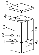
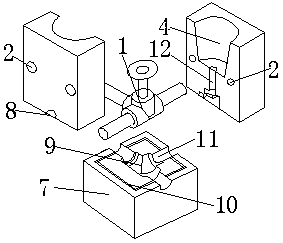
[0021] An exothermic welding mold comprises a left upper mold 3 and a lower mold 7; the inside of the upper mold 3 is provided with a reaction chamber 4 and a flow channel 12 for welding, and the contact surfaces of the upper mold 3 and the lower mold 7 are provided with There are welding cavities 9 matching each other, the reaction chamber 4 communicates with the welding cavities 9 through flow passages 12, and the periphery of the welding cavities 9 on the upper surface of the lower mold 7 is provided with strip grooves 10, The periphery of the welding cavity 9 on the lower surface of the upper mold 3 is provided with strip-shaped protrusions corresponding to the positions of the strip grooves 10, and the upper mold 3 is at least spliced ​​by two components 6 that match each other, and The interfitting components 6 are detachably and fixedly connected to each other. The upper mold 3 is spliced ​​by mutually matching components 6. During the welding process, when the solder i...

Embodiment 2

[0023] On the basis of Example 1, arc-shaped grooves 8 matching each other are provided on the contact surfaces of each component 6 of the upper mold 3 and the lower mold 7, and the arc-shaped grooves 8 are used for welding The cavities 9 are connected, and the arc-shaped groove 8 is also used to communicate with the sides of the upper mold 3 and the lower mold 7 . Each component 6 of the upper mold 3 and the arc-shaped groove 8 on the contact surface of the lower mold 7 form a circular through hole 11 on the side of the welding auxiliary device. This structure facilitates the welding of the workpiece 1 from the circular through hole 11 in or out.

Embodiment 3

[0025] On the basis of Examples 1-2, the longitudinal cross-sectional dimension of the strip-shaped protrusion is smaller than the longitudinal cross-sectional dimension of the strip-shaped groove 10 . The strip-shaped protrusions are used to fit in the strip-shaped grooves 10, and are used to ensure that each component 6 of the upper mold 3 does not shift with the lower mold 7, and ensure that the size of the welding cavity 9 is accurate, which is beneficial to welding without multiple times Only by adjusting the contact positions of each component 6 of the upper mold 3 and the lower mold 7 can the clamping of the upper mold 3 be carried out, which avoids the need to loosen and adjust the position of the welding cavity 9 after the upper mold 3 is clamped The trouble caused by re-clamping the upper mold 3, because the longitudinal cross-sectional dimension of the strip-shaped protrusion is smaller than the longitudinal cross-sectional dimension of the strip-shaped groove 10, su...


PUM


Abstract

The invention discloses heat-released welding die. The heat-released welding die comprises a left upper die and a lower die, wherein the interior of the upper die is provided with a reaction cavity used for welding and flow passages; welding cavities which are matched with each other are arranged on the contact surfaces of the upper die and the lower die respectively; the reaction cavity communicates with the welding cavities through the flow passages; strip-shaped grooves are formed in the peripheries of the welding cavities on the upper surface of the lower die; strip-shaped bulges corresponding to the strip-shaped grooves in positions are arranged on the peripheries of the welding cavities on the lower surface of the upper die; the upper die is formed by splicing at least two componentswhich are matched with each other; and the components which are matched with each other are detachable and fixedly connected mutually. In the welding process, when a welding flux is heated and expanded to enter into the reaction cavity, and after a structure that the upper die is difficult to take down from the upper die is formed through solidification, the upper die is split, the expanded welding flux in the reaction cavity and the welding cavities can be removed, and a workpiece is taken down.

Description

technical field [0001] The invention relates to a workpiece welding auxiliary device, in particular to an exothermic welding mold. Background technique [0002] Exothermic welding is a simple, high-efficiency, high-quality metal connection process. It uses the chemical reaction heat of metal compounds as a heat source, and through the overheated molten metal, directly or indirectly heats the work to form a certain amount in the cavity of a special mold. Fusion welded joints in shape, size, and engineering requirements. At present, exothermic welding has generally replaced the previous mechanical connection method between metals. However, in the actual implementation process of exothermic welding, because the upper mold of the known exothermic welding device is integral, although this kind of structure makes the processing of the exothermic welding device easier, it is relatively harsh due to the harsh environment of the welding site during use. , prone to adverse factors s...

Claims


Application Information

Patent Timeline
Patent Type & Authority Applications(China)
IPC IPC(8): B23K23/00
Inventor 刘楷
Owner CHENGDU KAILONG MACHINERY MAINTENANCE
Why Eureka
Try Eureka