Detection tool for detecting die part

A technology of parts and molds, which is applied in the field of inspection tools for mold parts inspection, can solve problems such as errors and low efficiency in detecting mold parts, and achieve the effects of convenient use, reduced processing costs, and improved inspection efficiency

Active Publication Date: 2020-09-18
重庆捷尔博模具科技有限公司
View PDF14 Cites 0 Cited by
  • Summary
  • Abstract
  • Description
  • Claims
  • Application Information

AI Technical Summary

Problems solved by technology

Some mold parts have a certain angle. Now the commonly used measurement method is: use a variety of detection tools (such as: angle ruler, cone gauge) to detect the angle of the mold parts. It is necessary to adjust the detection tools during detection, which is easy to adjust. There is a certain error
When testing different mold parts, the operator needs to make multiple adjustments, and the work efficiency of testing mold parts is not high, so it is necessary to improve the testing tools

Method used


Image

  • Detection tool for detecting die part
  • Detection tool for detecting die part
  • Detection tool for detecting die part

Examples


Embodiment 1

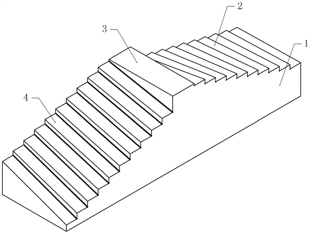
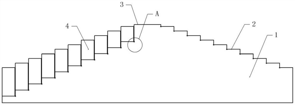
[0039] Basic as attached figure 1 , attached figure 2 And attached Figure 4 As shown, the inspection tool for mold parts inspection includes a boss 1. There are several inclined detection stations on both sides of the boss 1. The inspection station on the side of the boss 1 is inclined towards the front of the boss 1. The boss 1 1 The detection station on the other side is obliquely facing the back of the boss 1. The inclination angles of the detection stations gradually increase from top to bottom, and the inclination angles of two adjacent detection stations differ by 1°. In this embodiment, there are ten detection stations on each side of the boss 1, the inclination angle of the top detection station is 1°, and the inclination angle of the bottom detection station is 10°, that is, the inclination angle of the detection station is 1°. The tilt angle distribution is: 1°, 2°, 3°, 4°, 5°, 6°, 7°, 8°, 9°, 10°.

[0040] combined with image 3 As shown, there is an escape g...

Embodiment 2

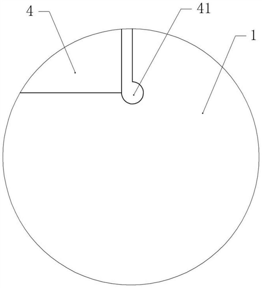
[0045] The difference between embodiment two and embodiment one is that, as attached Image 6 As shown, the main piece 411 and the secondary piece 412 are horizontally slidably connected in the avoidance groove 41, and the cross-sections of the main piece 411 and the secondary piece 412 are arc-shaped, and when the main piece 411 and the secondary piece 412 are fitted together, they can also form a Arc-shaped, the main sheet 411 and the secondary sheet 412 are bonded with elastic gaskets, and the elastic gaskets are made of rubber.

[0046] In this embodiment, when the thickness of the edges and corners of the mold part is B / C / D (B>C>D), when D is encountered, the elastic gasket can be deformed to a certain extent to adapt to the D thickness.

[0047] When the situation C is encountered, the main piece 411 or the secondary piece 412 can be taken out from the escape groove 41 to adapt to the C thickness.

[0048] When encountering condition B, the main piece 411 and the secondar...

Embodiment 3

[0051] The difference between embodiment three and embodiment one is that, as attached Figure 7 And attached Figure 8 As shown, some baffles 5 are arranged on both sides of the boss 1, and the baffles 5 are located at the low end side of the detection station (due to the inclination of the detection station, there are high and low ends), and the height of the baffles 5 varies with the detection position. The height of the workstation increases gradually, combined with the attached Figure 9 As shown, the baffle plate 5 includes an outer plate 51 and an inner plate 55, the inner plate 55 is located in the outer plate 51, the inner plate 55 is welded with a protrusion, the outer plate 51 is provided with a chute vertically slidingly connected with the protrusion, and the outer plate 51 A channel 53 is opened on the plate 51 , and an air hole 54 facing the escape groove 41 is communicated with the channel 53 , and a pressure relief valve 52 is fixed in the channel 53 by screws...


PUM


Abstract

The invention relates to the technical field of mold part detection, and discloses a detection tool for detecting a die part. The detection tool comprises a boss, and is characterized in that inclineddetection stations are arranged at the two sides of the boss; the inclination angle from the uppermost detection station to the lowermost detection station is gradually increased; a receding groove is formed between every two adjacent detection stations. The difference between the inclination angles of every two adjacent detection stations is 1 degree. The detection tool is simple in structure, and can quickly detect a plurality of die parts.

Description

technical field [0001] The invention relates to the technical field of mold parts detection, in particular to a checking tool for mold parts detection. Background technique [0002] After the mold parts are processed, the mold parts need to be inspected to determine whether the mold parts meet the standards after processing. Some mold parts have a certain angle. Now the commonly used measurement method is: use a variety of detection tools (such as: angle ruler, cone gauge) to detect the angle of the mold parts. It is necessary to adjust the detection tools during detection, which is easy to adjust. There are certain errors. When testing different mold parts, the operator needs to make multiple adjustments, and the work efficiency of testing mold parts is not high, so it is necessary to improve the testing tools. Contents of the invention [0003] The present invention intends to provide a testing tool for mold parts, which is used for testing mold parts and improves the ...

Claims


Application Information

Patent Timeline
Patent Type & Authority Applications(China)
IPC IPC(8): G01B5/24
CPCG01B5/24
Inventor 韦兴立
Owner 重庆捷尔博模具科技有限公司
Why Eureka
Try Eureka