
Adjusting type bearing frame for shaft machining

An adjustable and bearing frame technology, which is applied in the direction of metal processing equipment, metal processing machinery parts, manufacturing tools, etc., can solve the problems that cannot be adjusted according to needs, affect the precision of shaft processing, affect applicability and practicability, etc. To achieve the effect of ensuring the stability of placement, reliable top pressure position and good practicability

Pending Publication Date: 2018-01-26
浙江纳仕通电气有限公司
View PDF20 Cites 2 Cited by
  • Summary
  • Abstract
  • Description
  • Claims
  • Application Information

AI Technical Summary

Problems solved by technology

[0002] With the maturity of processing equipment technology, various processing equipment develops rapidly. In the process of shaft processing, it is necessary to clamp the reference end, and at the same time use the top of the tailstock to withstand the center hole for processing. However, due to the length of some shaft parts Long, so the center hole is damaged or deflected by the top of the tailstock during machining, which will affect the precision of shaft machining, and the position of the top of the tailstock and the processing seat is fixed, and cannot be adjusted according to needs, which will also affect its application sex and practicality

Method used


Image

  • Adjusting type bearing frame for shaft machining

Examples


Embodiment 1

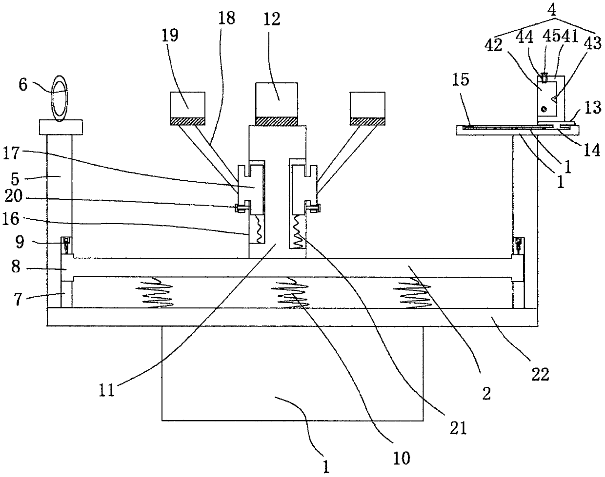
[0014] figure 1 A specific embodiment of the invention is shown in which figure 1 It is a structural schematic diagram of the present invention.

[0015] See figure 1 , an adjustable bearing frame for shaft processing, including a base frame 1 and a bearing seat 2 arranged on the base frame 1, a reference end clamping seat 3 is provided at one end of the bearing base 2, and the A clamping body 4 is fixed on the reference end clamp seat 3, a pressing seat 5 is provided at the other end of the bearing seat 2, a perforation 6 is arranged on the pressing seat 5 and the top is at the center of the perforation, so The center of the clamping body 4 is on the same straight line as the center of the perforation, and a vertical adjustment chute 7 is fixed on the inner surface of the pressing seat 5 and the reference end clamping seat 3, and on both sides of the bearing seat 2 The end is fixed with an I-shaped slider 8, and the I-shaped slider 8 is in the vertical adjustment chute 7, ...


PUM


Abstract

The invention discloses an adjusting type bearing frame for shaft machining. The adjusting type bearing frame comprises a bottom frame and a bearing seat arranged on the bottom frame. A datum end clamp seat is arranged at one end of the bearing seat. An abutting seat is arranged at the other end of the bearing seat. Vertical adjusting sliding grooves are fixed in the inner side face of the abutting seat and the inner side face of the datum end clamp seat. I-shaped sliding blocks are fixed to the two ends of the bearing seat. An adjusting air cylinder is fixed between the top face of each I-shaped sliding block and the top wall of the corresponding vertical adjusting sliding groove. A supporting bracket is fixed to the middle of the bearing seat. A V-shaped supporting plate is fixed to thetop of the supporting bracket. The datum end clamp seat comprises a base. A moving groove is formed in the top of the base. A clamping seat is arranged at the top of the base. A moving control air cylinder is fixed between an inverted-T-shaped moving block and the end wall of the moving groove. The adjusting type bearing frame is reasonable in structural arrangement, the machining precision can beguaranteed, meanwhile, the position of the clamping seat is adjusted according to needs, the application range of the adjusting type bearing frame is greatly widened, use stability is good, adaptability is high, and practicality is good.

Description

technical field [0001] The invention belongs to the technical field of processing equipment, and in particular relates to an adjustable bearing frame for shaft processing. Background technique [0002] With the maturity of processing equipment technology, various processing equipment develops rapidly. In the process of shaft processing, it is necessary to clamp the reference end, and at the same time use the top of the tailstock to withstand the center hole for processing. However, due to the length of some shaft parts Long, so the center hole is damaged or deflected by the top of the tailstock during machining, which will affect the precision of shaft machining, and the position of the top of the tailstock and the processing seat is fixed, and cannot be adjusted according to needs, which will also affect its application sex and practicality. Contents of the invention [0003] The object of the present invention is to provide an adjustable bearing frame with reasonable st...

Claims


Application Information

Patent Timeline
Patent Type & Authority Applications(China)
IPC IPC(8): B23Q1/76
Inventor 孔宇灿
Owner 浙江纳仕通电气有限公司
Learn More