A sub-frame connecting bush assembly, a sub-frame and an automobile
A sub-frame and bushing technology, which is applied in the connection between the body and the frame, vehicle parts, substructure, etc., can solve the problems of generalization of parts, poor economy, and non-adjustable inner sleeves, etc., and achieve good reliability. Replaceability, improved parts generalization rate, and good parts economy
- Summary
- Abstract
- Description
- Claims
- Application Information
AI Technical Summary
Problems solved by technology
Method used
Image
Examples
Embodiment 1
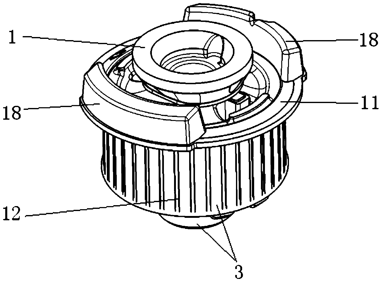
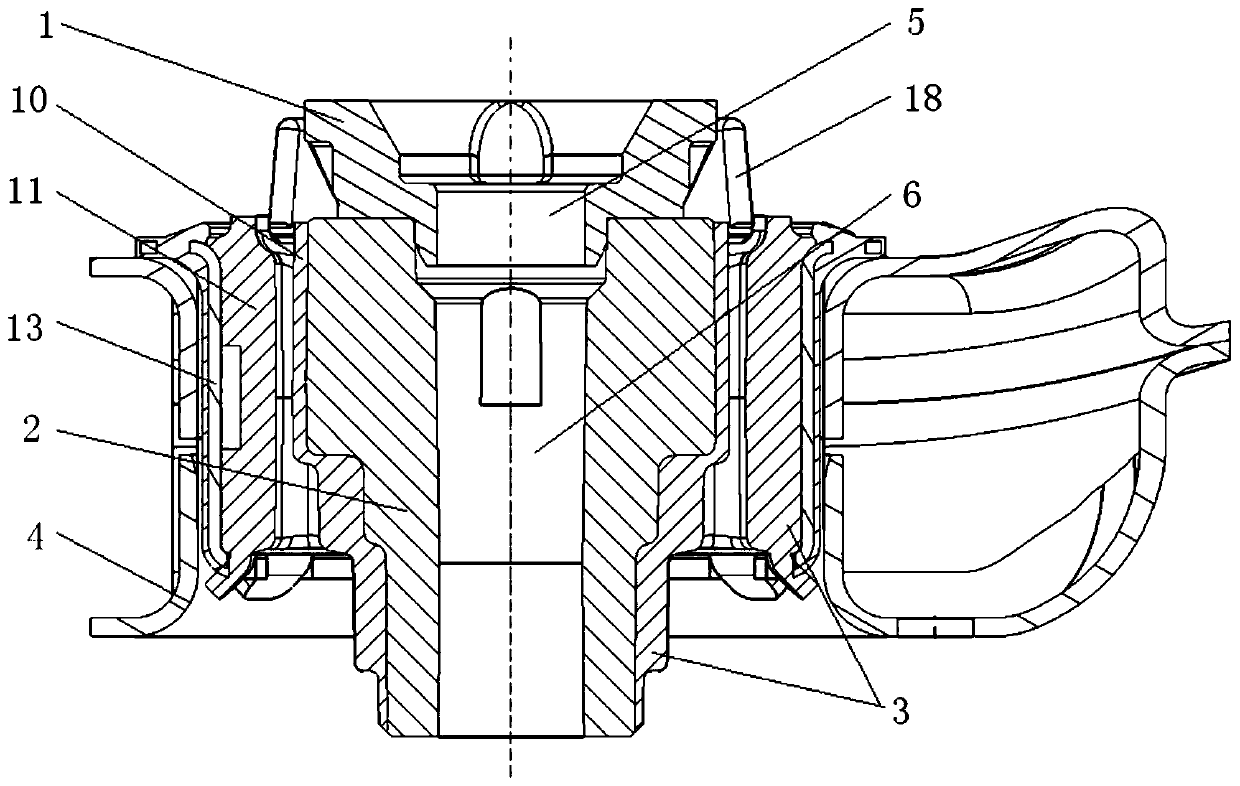
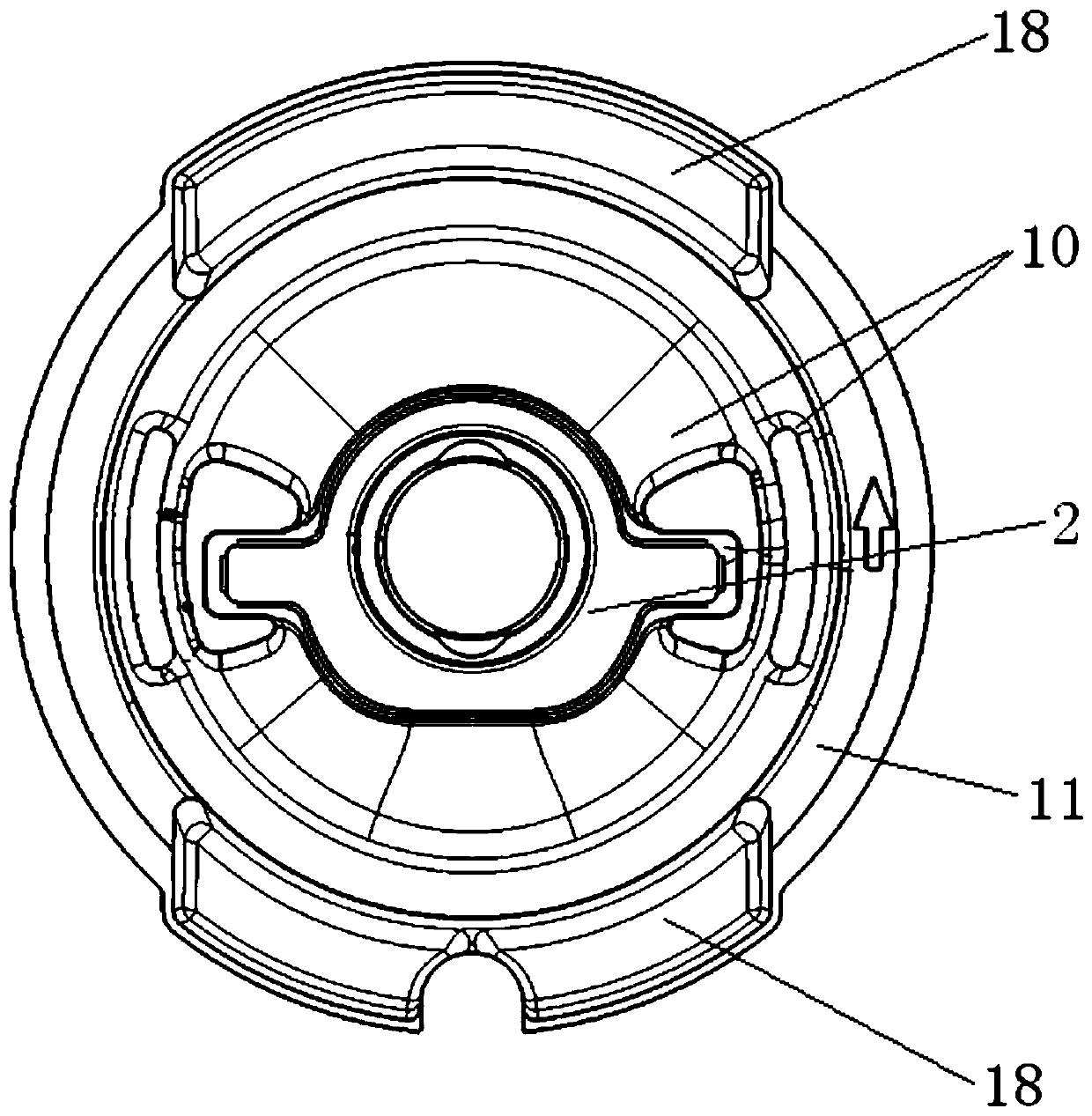
[0033] The invention provides a subframe connecting bush assembly. figure 1 It is a structural schematic diagram of Embodiment 1 of a sub-frame connecting bushing assembly of the present invention; figure 2 It is a connection diagram of Embodiment 1 of a sub-frame connection bushing assembly of the present invention and the installation hole of the sub-frame bushing; image 3 It is a connection diagram of the rubber body and the lower mandrel in Embodiment 1 of a subframe connection bushing assembly of the present invention; Figure 4 It is a structural schematic diagram of the inner frame in Embodiment 1 of a sub-frame connecting bushing assembly of the present invention; Figure 5 for Figure 4 sectional view of Image 6 It is a structural schematic diagram of the middle and lower mandrel in Embodiment 1 of a sub-frame connecting bushing assembly of the present invention; Figure 7 It is a structural schematic diagram of the upper mandrel in Embodiment 1 of a sub-frame ...
Embodiment 2
[0044] On the basis of the first embodiment, the present invention provides another subframe connecting bushing assembly. Figure 9 It is a structural schematic diagram of Embodiment 2 of a sub-frame connecting bushing assembly of the present invention; Figure 10 It is a structural schematic diagram of the limit bracket in Embodiment 2 of a sub-frame connecting bushing assembly of the present invention. The structure of this embodiment is the same as that of Embodiment 1, and will not be described here one by one, as Figure 9 with Figure 10 As shown, the difference between this embodiment and Embodiment 1 is that, on the basis of Embodiment 1, this embodiment adds a limit bracket 19;
[0045] Specifically: include a limit bracket 19, the limit bracket 19 is connected with a second buffer 20, the second buffer 20 is located at the bottom of the rubber body 3, the second buffer 20 has the same effect as the first buffer 18, and also It plays the role of flexible limit, pre...
Embodiment 3
[0051] The invention also provides a sub-frame, Figure 11 It is a structural schematic diagram of Embodiment 3 of a sub-frame of the present invention. Such as Figure 11 As shown, the subframe provided by the present invention includes the subframe connection bushing assembly and the subframe body 21 provided in the first or second embodiment above, wherein the structure and working principle of the subframe connection bushing assembly and main functions have been described in detail in the foregoing embodiments 1 and 2, and will not be repeated here.
[0052] The sub-frame provided by the present invention, by setting the sub-frame connecting bushing assembly, makes the limit stroke of the sub-frame connecting bushing assembly adjustable, improves the universalization rate of parts of the sub-frame connecting bushing, and increases the overall car comfort.
PUM
 Abstract
Description
Claims
Application Information
 - R&D
- Intellectual Property
- Life Sciences
- Materials
- Tech Scout
- Unparalleled Data Quality
- Higher Quality Content
- 60% Fewer Hallucinations
Browse by: Latest US Patents, China's latest patents, Technical Efficacy Thesaurus, Application Domain, Technology Topic, Popular Technical Reports.
© 2025 PatSnap. All rights reserved.Legal|Privacy policy|Modern Slavery Act Transparency Statement|Sitemap|About US| Contact US: help@patsnap.com


