H-shaped wheel tightening device for water tank wire-drawing machine

A technology of I-shaped wheel and water tank, which is applied in the field of I-shaped wheel tightening device of water tank wire drawing machine, which can solve problems such as flying out, disappearance of I-shaped wheel’s top tightening force, and injury to operators, and achieves simple power transmission structure and long-term guarantee Time running, stable and reliable effect

Active Publication Date: 2018-01-30
湖北三江航天江北机械工程有限公司
View PDF5 Cites 1 Cited by
  • Summary
  • Abstract
  • Description
  • Claims
  • Application Information

AI Technical Summary

Problems solved by technology

[0003] However, in the process of using the traditional cylinder jacking device, there have always been defects such as large space occupation, easy damage to parts, difficult repair and replacement, and poor maintainability, resulting in a high failure rate of equipment and a high scrap rate of products produced. The labor intensity of the maintenance staff is high
In addition, there are certain potential safety hazards. When the air source pipeline fails, the clamping force of the I-shaped wheel will suddenly disappear, and the high-speed rotating I-shaped wheel may fly out of the equipment, causing injury to the operator.

Method used


Image

  • H-shaped wheel tightening device for water tank wire-drawing machine
  • H-shaped wheel tightening device for water tank wire-drawing machine
  • H-shaped wheel tightening device for water tank wire-drawing machine

Examples


Embodiment Construction

[0033] The present invention will be further described in detail below in conjunction with the accompanying drawings and specific embodiments.

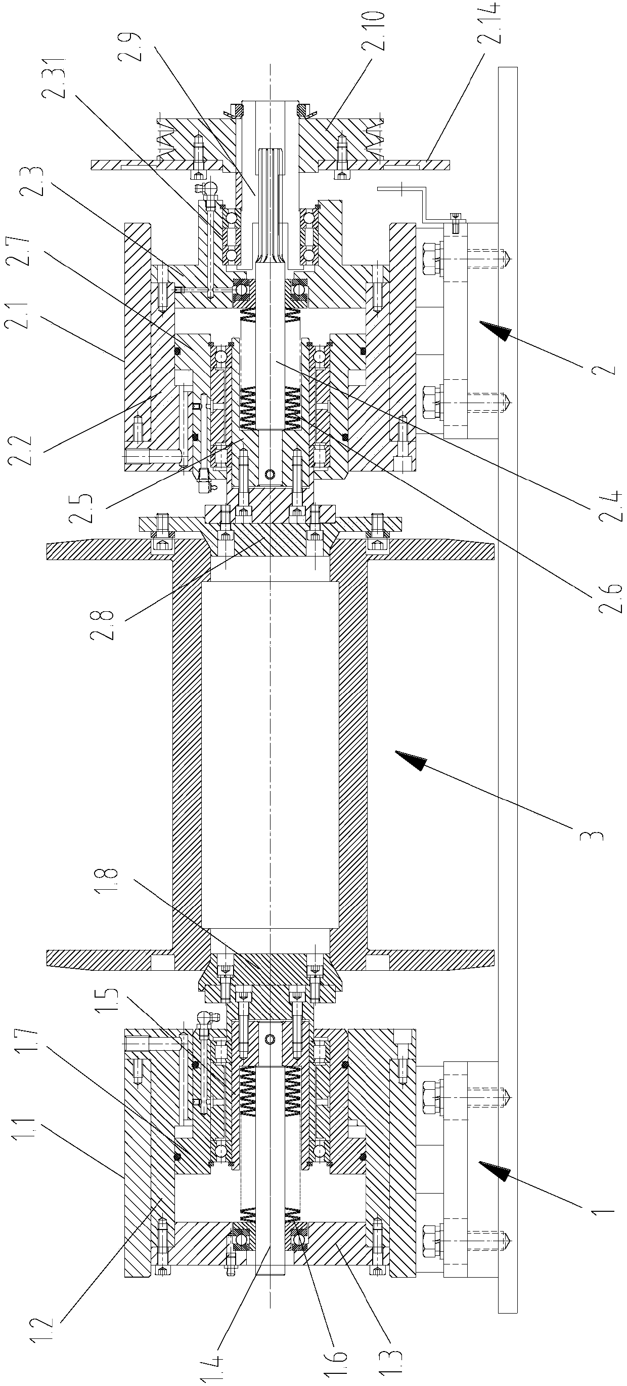
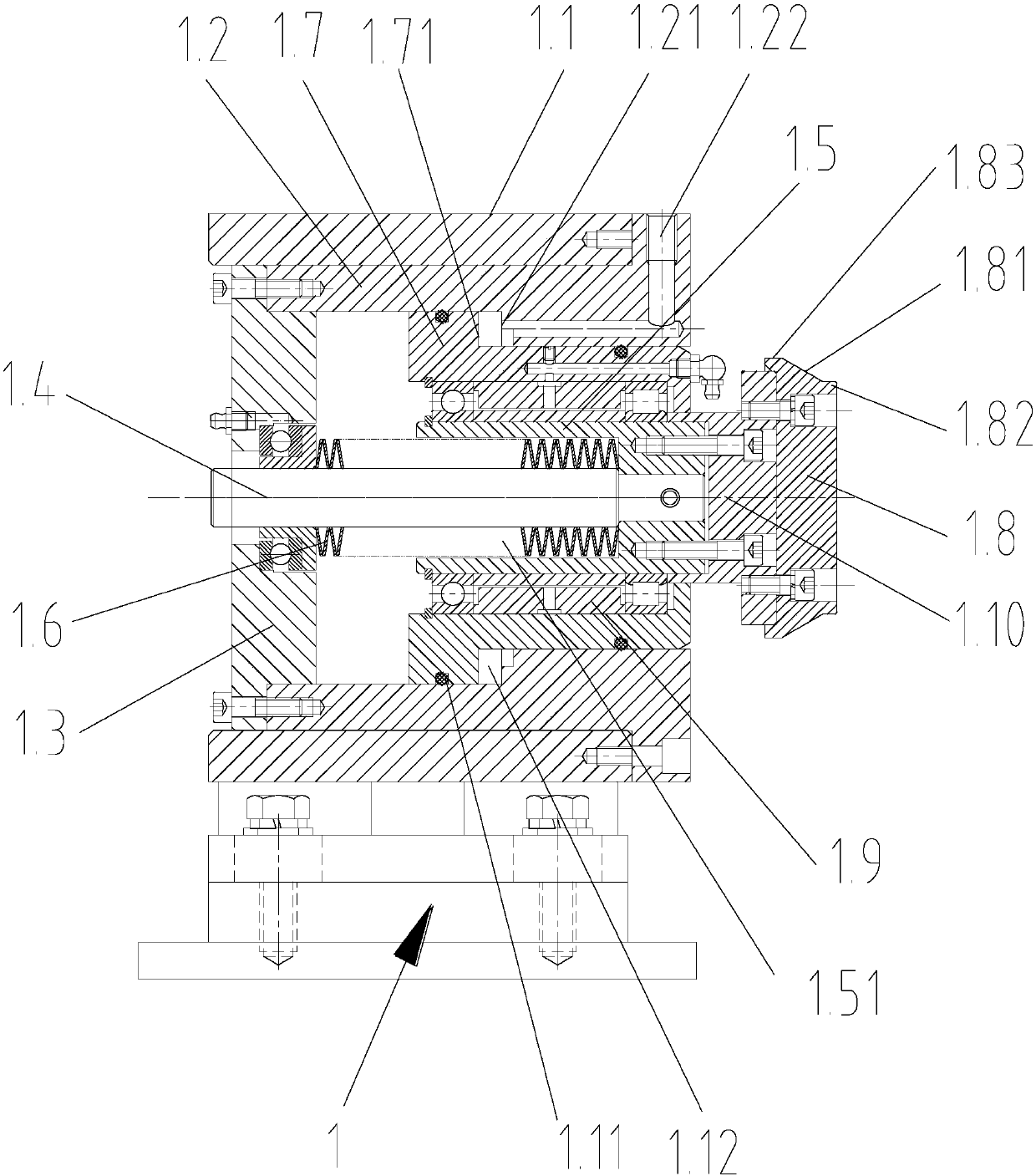
[0034] As shown in the figure, an I-wheel tightening device for a water tank wire drawing machine includes a first disc spring tightening mechanism 1 and a second disc spring tightening mechanism 2 arranged at both ends of the I-wheel 3 in the axial direction. The first disc spring tightening mechanism 1 includes a cylindrical first mounting seat 1.1, a first fixing sleeve 1.2 arranged circumferentially on the inner cavity of the first mounting seat 1.1 and its inner wall, One end of the inner cavity is fixed to the first end cover 1.3 of the first fixed sleeve 1.2 in the circumferential direction, and the first sliding shaft 1.4 axially penetrates the middle part of the inner cavity of the first mounting base 1.1; one end of the first sliding shaft 1.4 runs through the first The center hole of the end cover 1.3 is slidingly matched wit...


PUM

PropertyMeasurementUnit
diameteraaaaaaaaaa
diameteraaaaaaaaaa

Abstract

The invention discloses an H-shaped wheel tightening device for a water tank wire-drawing machine. The tightening device comprises a first disc spring tightening mechanism and a second disc spring tightening mechanism which are symmetrically arranged at two ends of an H-shaped wheel in the axial direction. The first disc spring tightening mechanism comprises a first cylindrical mounting seat, a first fixing sleeve, a first end cap and a first sliding shaft; the first fixing sleeve is annularly arranged on a cavity of the first mounting seat and is attached to the inner wall of the cavity; thefirst end cap is arranged at one end of the cavity of the first mounting seat; the first end cap and the first fixing sleeve are fixed in the circumferential direction; and the first sliding shaft penetrates in the middle of the cavity of the first mounting seat in the axial direction. The second disc spring tightening mechanism comprises a second cylindrical mounting seat, a second fixing sleeve,a second end cap and a second sliding shaft, wherein the second fixing sleeve is annularly arranged on a cavity of the second mounting seat and is attached to the inner wall of the second mounting seat; the second end cap is arranged at one end of the cavity of the second mounting seat; the second end cap and the second fixing sleeve are fixed in the circumferential direction; and the second sliding shaft penetrates in the middle of the cavity of the second mounting seat in the axial direction. The H-shaped wheel tightening device for the water tank wire-drawing machine is simple in structure, and is safe and reliable, and thus, the working efficiency of rolling of steel cords is ensured.

Description

technical field [0001] The invention relates to an I-wheel tightening device, in particular to an I-wheel tightening device for a water tank wire drawing machine. Background technique [0002] With the rapid development of urbanization and industrialization, the demand for cable equipment is increasing. The water tank wire drawing machine equipment belonging to the steel cord equipment is also developing rapidly. At present, the I-wheel jacking method of the water tank wire drawing machine is the cylinder jacking method. The top cone in the cylinder tightening device is usually directly tightened by the cylinder, which is used to tighten and position the two ends of the rotating I-wheel to complete the winding work of the cable. [0003] However, in the process of using the traditional cylinder jacking device, there have always been defects such as large space occupation, easy damage to parts, difficult repair and replacement, and poor maintainability, resulting in a high f...

Claims


Application Information

Patent Timeline
Patent Type & Authority Applications(China)
IPC IPC(8): B21C47/28B21C47/02
Inventor 周萌赖银燕朱国刚豆晓彤
Owner 湖北三江航天江北机械工程有限公司
Why Eureka
Try Eureka