
Throttling valve and engine

A throttling valve and throttling technology, applied in the direction of engine control, machine/engine, mechanical equipment, etc., can solve the problems of high combustion stability, unstable engine speed, and inconvenient engine calibration.

Active Publication Date: 2018-01-30
WEICHAI POWER CO LTD
View PDF7 Cites 5 Cited by
  • Summary
  • Abstract
  • Description
  • Claims
  • Application Information

AI Technical Summary

Problems solved by technology

The circulation area will affect the intake air volume and fuel supply volume of the engine, and the engine will show unstable idling speed and insensitive engine control at high loads (sudden load unloading is prone to over-speed parking, sudden load engine suffocation, etc.) , the horizontal bar cycle changes (IMEP_COV, combustion stability) are relatively large, etc.
[0004] The traditional throttle valve is limited by its structure, and has the characteristics of insufficient control accuracy at small openings and insensitive control at large openings
On the engine, the performance is that the engine speed is unstable when idling, the engine speed drops sharply when the load is suddenly added, or the engine is suffocated, which also brings a lot of inconvenience and difficulty to the engine calibration.

Method used


Image

  • Throttling valve and engine
  • Throttling valve and engine
  • Throttling valve and engine

Examples


Embodiment Construction

[0023] The invention discloses a throttling valve, which improves the control accuracy of the opening degree of the throttling device; the invention also provides an engine.

[0024] The technical solutions in the embodiments of the present invention will be clearly and completely described below in conjunction with the accompanying drawings in the embodiments of the present invention. Obviously, the described embodiments are only some, not all, embodiments of the present invention. Based on the embodiments of the present invention, all other embodiments obtained by persons of ordinary skill in the art without making creative efforts fall within the protection scope of the present invention.

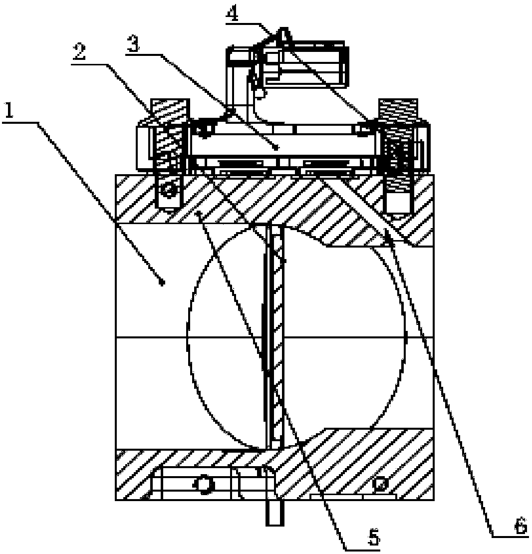
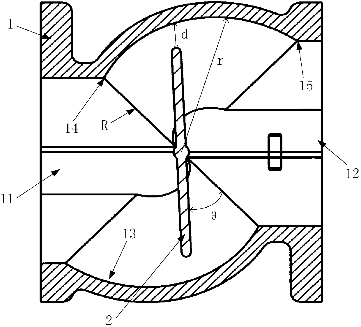
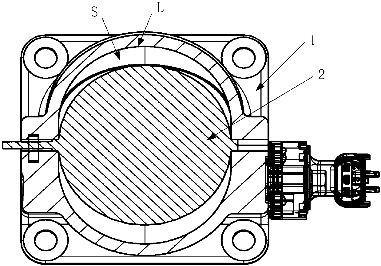
[0025] Such as figure 1 as shown, figure 1 A cross-sectional view of the structure of the throttle valve provided by the present invention; figure 2 The front structural sectional view of the throttle valve provided by the present invention; image 3 for figure 2 Right-view structu...


PUM


Abstract

The invention provides a throttling valve. The throttling valve comprises a throttling valve shell and a valve plate erected inside the throttling valve shell, the throttling valve shell comprises a valve inlet, a valve outlet and a throttling area arranged between the valve inlet and the valve outlet, and the valve plate is erected on the throttling area; a throttling initial point which is in cooperation with the valve plate when the valve plate is closed and a throttling end point which is in cooperation with the valve plate when the valve plate is totally opened are arranged on the inner wall of the throttling valve shell, and a throttling hook face which is in arc transition to the throttling end point from the throttling initial point is further arranged on the inner wall of the throttling valve shell. The throttling hook face which is in arc transition to the throttling end point from the throttling initial point is arranged on the inner wall of the throttling valve shell, alongwith the rotation of the valve plate, the spacing between the end of the valve plate and the throttling hook face is in uniform transition, the opening range control is more accurate, the situation that throttling of the throttling valve is unstable due to sudden change of the throttling area of the valve plate is avoided, the throttling control precision is higher, and the controlling precisionof the throttling valve is improved. The invention further provides an engine provided with the throttling valve structure.

Description

technical field [0001] The invention relates to the technical field of throttle valves, more specifically, to a throttle valve and an engine. Background technique [0002] Various valve bodies such as air intake throttle valve, gas trim valve and EGR valve are usually arranged in the engine. The intake throttle valve is used on the engine intake pipe to control the entry of air or fuel-air mixture into the engine. Gas Trim Valves (Trim usually stands for Valve Trim) are used on engine fuel supply systems to control the flow of fuel into the intake manifold or engine. The EGR valve is used between the engine exhaust system and the intake system to control the exhaust gas in the exhaust pipe from entering the intake pipe. [0003] The shells of the existing air intake throttle valve and gas trim valve are tubular, and the shape of the inner valve plate is usually circular. When the opening of the valve plate is small, the opening of the valve plate changes little, but the f...

Claims


Application Information

Patent Timeline
IPC IPC(8): F02D9/10
Inventor 李旺徐帅卿赵巍
Owner WEICHAI POWER CO LTD
Learn More