A Real-time Dynamic Cloud Cover Inversion Method Based on Ground-Based Cloud Image

A ground-based cloud image and cloud image technology, which is applied in image analysis, image enhancement, image data processing, etc., can solve the problems of large inversion cloud amount error, long atmospheric transmission path, and large environmental impact, and achieve the effect of improving accuracy

Active Publication Date: 2020-04-24
NORTHWEST INST OF ECO ENVIRONMENT & RESOURCES CAS +1
View PDF5 Cites 0 Cited by
  • Summary
  • Abstract
  • Description
  • Claims
  • Application Information

AI Technical Summary

Problems solved by technology

However, when the sky is clear and the cloud cover is low, due to the influence of aerosols and air masses, the atmospheric transmission path is long, making the pixels in the heliosphere and near-horizon region look whiter and brighter. The current method uses these points as clouds when processing images. Point processing, so that the cloud amount calculated in the case of clear sky and less cloud has error
Moreover, the red-blue ratio of the ground-based cloud image of the all-sky imager is greatly affected by the atmosphere (aerosol content, dust, visibility, etc.) and the environment. Therefore, this method cannot effectively identify cloud and sky pixels in complex weather conditions, making the inversion Large error in cloud amount

Method used


Image

  • A Real-time Dynamic Cloud Cover Inversion Method Based on Ground-Based Cloud Image
  • A Real-time Dynamic Cloud Cover Inversion Method Based on Ground-Based Cloud Image
  • A Real-time Dynamic Cloud Cover Inversion Method Based on Ground-Based Cloud Image

Examples


Embodiment 1

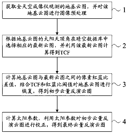
[0040] A real-time dynamic cloud cover inversion method based on ground-based cloud images. The ground-based cloud images can be derived from all-sky imager sites that are matched and deployed by multiple photovoltaic power plants. Refer to figure 1 , the method may specifically include the following steps:

[0041] (1) Obtain the ground-based cloud image observed by the all-sky imager in real time, and perform image preprocessing on the ground-based cloud image.

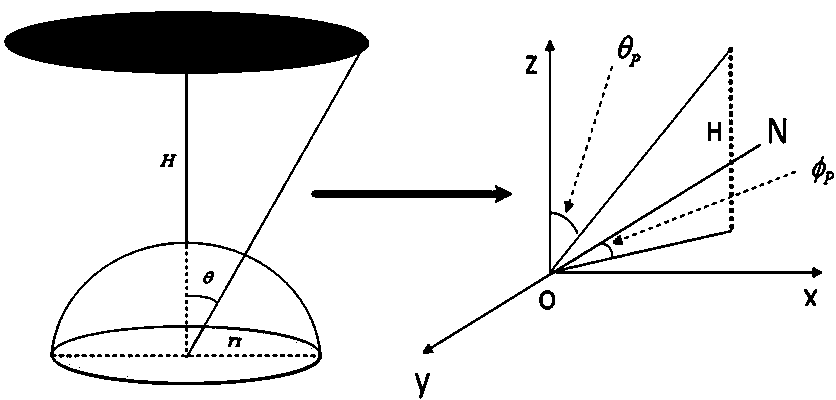
[0042] Wherein, the image preprocessing specifically includes occlusion recovery processing and coordinate transformation processing; wherein, coordinate transformation refers to the transformation from the image coordinate system to the sky coordinate system.

[0043] Cloud image occlusion recovery can refer to the following content: There are usually two parts of occlusion on the ground-based cloud image, namely the lens bracket and the projection of the shading belt. The position of the projection part of the br...

Embodiment 2

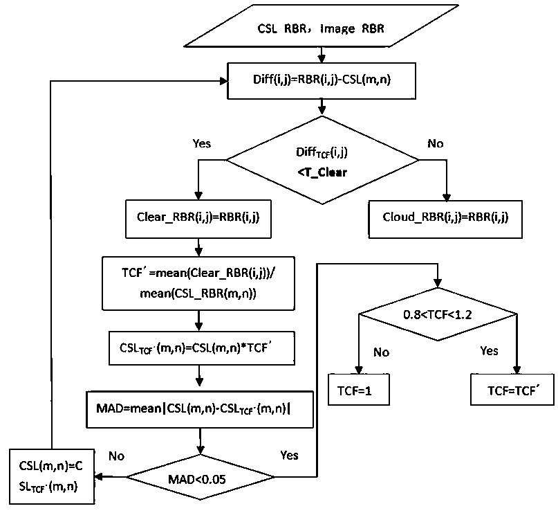
[0064] Based on the technical solution disclosed in the above-mentioned embodiment 1, the above step (2) selects the corresponding latest cloud image in the clear sky database according to the solar zenith angle of the ground-based cloud image, and uses the latest cloud image to calculate the atmospheric turbidity correction factor TCF, refer to image 3 , which can specifically include the following:

[0065] (21) Traverse the pixel red-blue ratio RBR(i,j) of the ground-based cloud image and the corresponding pixel red-blue ratio CSL(m,n) of the latest cloud image, and calculate Diff(i,j)=RBR(i,j)- one by one CSL(m,n), and according to the relationship between Diff(i,j) and the clear-air threshold M (T_Clear in the figure), filter out the clear-sky pixels in the ground-based cloud image.

[0066] Among them, CSL TCF (m,n)=CSL(m,n)*TCF, PZA(i,j)=PZA(m,n), SPA(i,j)=SPA(m,n), refer to Figure 4 , PZA is the pixel zenith angle, SPA is the angle between the pixel and the sun, th...

Embodiment 3

[0077] Based on the content disclosed in the above-mentioned embodiments, step (3) in embodiment 1 calculates the pixel red-blue ratio difference between the ground-based cloud image and the latest cloud image, and combines the TCF and the preset red-blue ratio threshold to restore the ground-based cloud image, and obtains Preliminary cloud cover inversion cloud map, including the following contents:

[0078] (31) Traverse the pixel red-blue ratio RBR(i,j) of the ground-based cloud image and the corresponding pixel red-blue ratio CSL(m,n) of the latest cloud image, and calculate Diff one by one TCF (i,j)=RBR(i,j)-CSL TCF (m,n).

[0079] Among them, CSL TCF (m,n)=CSL(m,n)*TCF, refer to Embodiment 2 for other related content.

[0080] (32) According to Diff TCF The relationship between (i, j) and the red-blue ratio threshold value identifies the pixel type of each pixel point (i, j) on the ground-based cloud image.

[0081] Specifically, the identification process is consis...


PUM


Abstract

The invention relates to a real-time dynamic cloud cover inversion method based on a foundation cloud image. The method comprises the steps that (1) the foundation cloud image observed by an all-sky imager is acquired in real time, and image preprocessing is carried out on the foundation cloud image; (2) a corresponding latest cloud image is selected in a clear sky database according to the solarzenith angle of the foundation cloud image, and the atmospheric turbidity correction factor TCF is calculated; (3) the pixel red-blue ratio difference between the foundation cloud image and the latestcloud image is calculated, and the TCF and a preset red-blue ratio threshold is combined to recover the foundation cloud image to acquire an initial cloud cover inversion cloud image; and (4) solar parameters of the foundation cloud image are calculated, and the solar parameters are used to correct pixels near the solar circle in the initial cloud cover inversion cloud image to acquire the finalcloud cover inversion cloud image. According to the invention, the atmospheric turbidity correction factor TCF and the solar parameters are introduced to correct the influence of the environment on the red-blue ratio; the accuracy of cloud cover inversion is effectively improved; and the true cloud cover distribution in the sky is inversed.

Description

technical field [0001] The invention relates to the field of ground-based remote sensing cloud technology, in particular to a real-time dynamic cloud amount inversion method based on ground-based cloud images. Background technique [0002] With the global energy crisis and environmental pollution becoming increasingly prominent, the scale of solar energy development and utilization has rapidly expanded, and it has become an important field of global energy transformation. The "Thirteenth Five-Year Plan for Solar Energy Development" proposes that the cumulative installed capacity of photovoltaic power generation in the country will increase from 860,000 kilowatts in 2010 to 43.18 million kilowatts in 2015, and 15.13 million kilowatts of new installed capacity will be added in 2015. By the end of 2020, the installed capacity of solar power will reach More than 110 million kilowatts. Ground irradiance is the most direct meteorological factor that determines the output of photo...

Claims


Application Information

Patent Timeline
Patent Type & Authority Patents(China)
IPC IPC(8): G06T7/00G06T5/00
Inventor 蒋俊霞高晓清汪宁渤吕清泉李振朝杨丽薇
Owner NORTHWEST INST OF ECO ENVIRONMENT & RESOURCES CAS
Why Eureka
Try Eureka