
A load-bearing and shock-absorbing device for a bicycle

A shock absorber and bicycle technology, applied in the direction of spring/shock absorber, vibration suppression adjustment, non-rotational vibration suppression, etc., can solve problems such as inability to completely eliminate vibration, lack of shock absorption effect, weak shock absorption effect, etc. Achieve good damping and stiffness, good shock absorption effect, and stable shell

Inactive Publication Date: 2019-11-29
阜阳正林新能源科技有限公司
View PDF8 Cites 0 Cited by
  • Summary
  • Abstract
  • Description
  • Claims
  • Application Information

AI Technical Summary

Problems solved by technology

[0003] However, the current shock absorbing device has the following problems: 1) the shock absorbing effect of ordinary shock absorbing pads is relatively weak, and even does not achieve the shock absorbing effect; 2) the shock absorbing pads will be worn during use, and the wear will cause bicycle During the movement, the walking is not stable; 3) springs are often used as buffer elements now. After the spring absorbs the kinetic energy of the vibration, it is converted into the potential energy of the spring, thereby buffering the impact of the ground on the bicycle, but the spring itself does not consume energy. When the spring returns to its original state, the potential energy of the spring becomes kinetic energy again, which will produce a bouncing effect on the bicycle; If the device is added to the parts of the bicycle, the effect is not obvious

Method used


Image

  • A load-bearing and shock-absorbing device for a bicycle
  • A load-bearing and shock-absorbing device for a bicycle
  • A load-bearing and shock-absorbing device for a bicycle

Examples


Embodiment

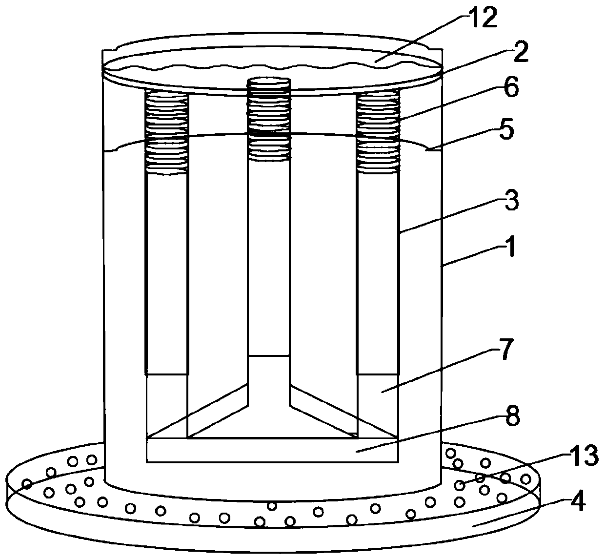
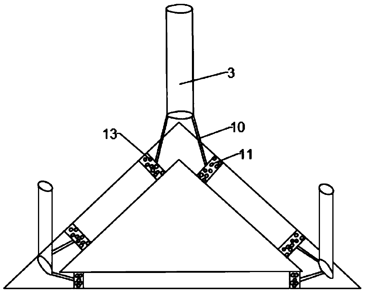
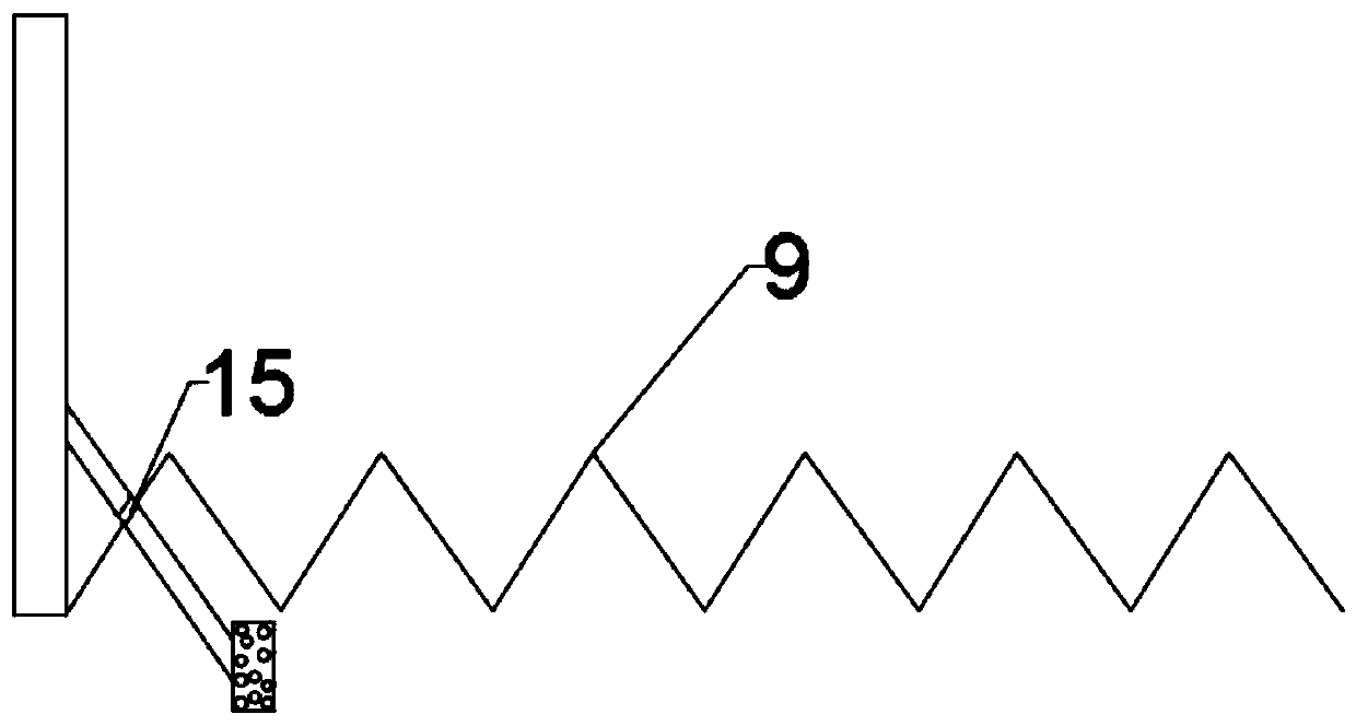
[0019] like figure 1 , figure 2 and image 3 As shown, the present invention provides a load-bearing and shock-absorbing device for a bicycle, which includes a cylindrical sleeve 1, a circular vibration transmission plate 2, a guide sleeve 3 and a lead rubber base 4, and the cylindrical sleeve 1 is nested in the lead core In the rubber base 4, the upper end of the cylindrical sleeve 1 is provided with upper and lower limit rings 5, the circular vibration transmission plate 2 is installed between the upper and lower limit rings 5, and the lower surface of the circular vibration transmission plate 2 is fixedly connected Three guide sleeves 3, the guide sleeves 3 are distributed in an equilateral triangle with respect to the center of the circular vibration transmission plate 2, a spring 6 is arranged inside the guide sleeve 3, and one end of the spring 6 is connected to the circular vibration transmission plate 2 fixedly connected, the other end of the spring 6 is connected w...


PUM


Abstract

The invention discloses a load bearing and shock absorbing device of a bicycle. The load bearing and shock absorbing device comprises a cylindrical sleeve, a circular vibration transmission plate, guide sleeves and a lead-core rubber base; the cylindrical sleeve is embedded in the lead-core rubber base; upper and lower limiting rings are arranged at the upper end of the cylindrical sleeve; the circular vibration transmission plate is mounted between the upper and lower limiting rings; the lower surface of the circular vibration transmission plate is fixedly connected with the guide sleeves; springs are arranged in the guide sleeves; one end of each spring is fixedly connected with the circular vibration transmission plate, the other end of the spring is connected with a supporting column;a hydraulic tank is arranged on the upper surface of the lead-core rubber base; the position of the hydraulic tank is the same as those of the guide sleeves; the supporting columns are fixedly mountedon three corners of the hydraulic tank; a tank cover is fixedly connected with the hydraulic tank; moving rods are arranged at the bottoms of the guide sleeves; and the other end of each moving rod penetrates through the tank cover to be fixedly connected with a sliding plate. The load bearing and shock absorbing device is stable and reasonable in structure, the shock absorbing effect is realizedthrough combination of the springs, hydraulic vibration elimination and lead-core rubber, and the device has the certain load bearing ability.

Description

technical field [0001] The invention relates to the technical field of bicycles, in particular to a load-bearing and shock-absorbing device for bicycles. Background technique [0002] A bicycle, also known as a bicycle or bicycle, is usually a small land vehicle with two wheels. After a person rides on the car, it is powered by pedals, which is a green and environmentally friendly means of transportation. There are many types of bicycles, including single bicycles, tandem bicycles and multi-person bicycles. It can be used as an environmentally friendly means of transportation for transportation and travel; more and more people use bicycles as fitness equipment for cycling exercise and bicycle travel; bicycle itself is also a competitive sport, including road cycling, mountain biking, Track cycling competitions, stunt bicycle competitions, etc. When we travel by bicycle, we will inevitably encounter uneven roads. In order to have a better experience when riding bicycles and...

Claims


Application Information

Patent Timeline
Patent Type & Authority Patents(China)
IPC IPC(8): F16F15/023F16F15/08
CPCF16F15/023F16F15/046F16F15/08
Inventor 钱丽艳
Owner 阜阳正林新能源科技有限公司
Learn More