Lightning protecting and lightning arresting device integrated on vehicle-mounted antenna

A vehicle-mounted antenna and lightning protection device technology, applied in the direction of antenna, antenna components, antenna grounding switch structure connection, etc., can solve the problems of lightning current discharge lightning energy, uneven distribution, direct lightning strike, etc., to reduce the probability of lightning strikes , the effect of changing the lightning protection method

Inactive Publication Date: 2018-02-02
葛彪
View PDF0 Cites 0 Cited by
  • Summary
  • Abstract
  • Description
  • Claims
  • Application Information

AI Technical Summary

Problems solved by technology

[0002] The traditional lightning rod is installed at the highest point of the lightning protection object. When lightning occurs, this highest point and the thundercloud form an extremely unevenly distributed electric field environment, which makes the air between the thundercloud and the lightning rod easy to be broken down, and the lightning current is extremely high. Easy to discharge lightning energy to the earth through the lightning rod
In fact, this lightning protection method that discharges lightning energy by guiding the lightning to itself is more likely to cause direct lightning strikes. The traditional lightning rod that guides the lightning to itself and discharges lightning energy to the ground cannot provide protection for cars, especially vehicle-mounted antennas. Ray provides security

Method used


Image

  • Lightning protecting and lightning arresting device integrated on vehicle-mounted antenna

Examples


Embodiment Construction

[0015] The present invention will be further described below in conjunction with the accompanying drawings. The following examples are only used to illustrate the technical solution of the present invention more clearly, but not to limit the protection scope of the present invention.

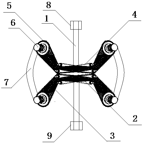
[0016] figure 1 It is a structural representation of the present invention. The invention provides a lightning protection and lightning protection device integrated on a vehicle-mounted antenna, which is characterized in that it includes a vehicle-mounted antenna 1 and a lightning protection bracket 2, the lightning protection bracket 2 is fixedly arranged on the vehicle-mounted antenna 1, and the lightning protection bracket 2 is provided with symmetrical Distributed lightning rod cover 3.

[0017] As a preferred embodiment, there are four lightning rod sleeves 3 distributed symmetrically with each other.

[0018] As a preferred embodiment, the lightning rod cover 3 is hinged on the lightnin...


PUM


Abstract

The invention discloses a lightning protection and lightning protection device integrated on a vehicle-mounted antenna, which is characterized in that it comprises a vehicle-mounted antenna and a lightning protection bracket, the lightning protection bracket is fixedly arranged on the vehicle-mounted antenna, and the lightning protection bracket is provided with There are lightning protection rod sets with symmetrical distribution. The present invention is applied in the technical field of lightning protection and lightning protection of vehicle-mounted antennas on automobiles. Lightning protection brackets and symmetrically distributed lightning protection rod sleeves are installed on the vehicle-mounted antennas of automobiles through hinged rods, and connected by setting the upper and lower ends of the vehicle-mounted antennas. The head and the lower connecting head are fixed on the top of the car, and then the left and right symmetrical and interconnected lightning protection caps and connecting bending rods are arranged on the lightning protection rod sleeve. By forming an evenly distributed induction charge layer around the lightning protection cap and connecting bending rods, By forming a relatively evenly distributed electric field environment in the induced charge layer and thunderclouds, the probability of lightning strikes is significantly reduced, and the lightning protection method that induces lightning to itself is fundamentally changed to achieve the beneficial effect of effective lightning protection for the car's on-board antenna.

Description

technical field [0001] The invention relates to a lightning protection and lightning protection device integrated on a vehicle-mounted antenna, which belongs to the technical field of the automobile industry. Background technique [0002] The traditional lightning rod is installed at the highest point of the lightning protection object. When lightning occurs, this highest point and the thundercloud form an extremely unevenly distributed electric field environment, which makes the air between the thundercloud and the lightning rod easy to be broken down, and the lightning current is extremely high. Easy to discharge lightning energy to the earth through the lightning rod. In fact, this lightning protection method that discharges lightning energy by guiding the lightning to itself is more likely to cause direct lightning strikes. The traditional lightning rod that guides the lightning to itself and discharges lightning energy to the ground cannot provide protection for cars, e...

Claims


Application Information

Patent Timeline
IPC IPC(8): H01Q1/50H01Q1/32
CPCH01Q1/50H01Q1/3216
Inventor 葛彪
Owner 葛彪
Why Eureka
Try Eureka