Radio-frequency signal emission antenna

A technology of radio frequency signal and transmitting antenna, applied in the field of communication, can solve the problems of fixed antenna, easy to be struck by lightning, reducing the signal receiving range, etc.

Active Publication Date: 2019-07-16
广西电网有限责任公司来宾供电局 +1
View PDF10 Cites 0 Cited by
  • Summary
  • Abstract
  • Description
  • Claims
  • Application Information

AI Technical Summary

Problems solved by technology

[0002] Some signal receivers on the ground receive radio frequency signals through their receiving devices for normal use of the equipment. The radio frequency signal transmitters are generally installed at high places, and the signals emitted by them can be received by a wide range of signal receivers. Due to the signal reception The antenna is installed at a high place. When encountering bad weather, especially lightning weather, it is vulnerable to lightning strikes, while the traditional antenna is fixed, which reduces the signal receiving range.

Method used


Image

  • Radio-frequency signal emission antenna
  • Radio-frequency signal emission antenna
  • Radio-frequency signal emission antenna

Examples


Embodiment Construction

[0016] All features disclosed in this specification, or steps in all methods or processes disclosed, may be combined in any manner, except for mutually exclusive features and / or steps.

[0017] Any feature disclosed in this specification (including any appended claims, abstract and drawings), unless expressly stated otherwise, may be replaced by alternative features which are equivalent or serve a similar purpose. That is, unless expressly stated otherwise, each feature is one example only of a series of equivalent or similar features.

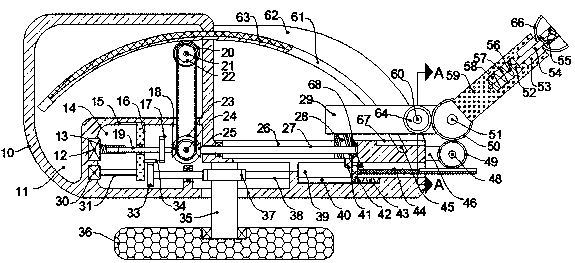
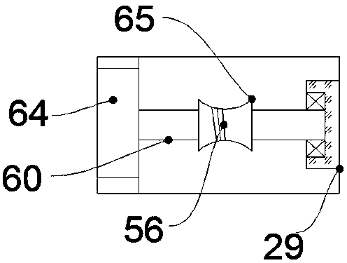
[0018] like Figure 1-2 As shown, a radio frequency signal transmitting antenna of the device of the present invention includes a storage box 10 and a storage cavity 62 arranged in the storage box 10, and a mechanical arm device is arranged in the storage cavity 62, and the mechanical arm device includes The fixed arm 29 and the rotating arm 59 that cooperates with the fixed arm 29 through the deployment gear shaft 51, the rotation arm 59 can...


PUM


Abstract

A radio-frequency signal emission antenna comprises a storage box and a storage cavity, wherein the storage cavity is formed in the storage box, a mechanical arm device is arranged in the storage cavity and comprises a fixed arm and a rotation arm, the rotation arm is matched with the fixed arm by an expansion gear shaft, the rotation arm can rotate around the expansion gear shaft, the mechanicalarm device comprises a displacement mechanism, and the displacement mechanism is matched with the fixed arm. The device is simple in mechanism and is simple and convenient to use, the device can be started in severe weather such as thunderstorm and high wind to storage a signal antenna; after storage, the wind receiving area can be reduced by the device, and the danger that the signal antenna is blown away is greatly prevented; moreover, after the device is stored, an enclosed box body material is an insulation material, the probability of lightning strike is greatly reduced, and the application safety is ensured; and meanwhile, the device also can be used for automatically rotating and adjusting, and a user is convenient to rapidly adjust an angle when no signal is generated.

Description

technical field [0001] The invention relates to the technical field of communication, in particular to a radio frequency signal transmitting antenna. Background technique [0002] Some signal receivers on the ground receive radio frequency signals through their receiving devices for normal use of the equipment. The radio frequency signal transmitters are generally installed at high places, and the signals emitted by them can be received by a wide range of signal receivers. Due to the signal reception The antenna is installed at a high place, and it is easy to be struck by lightning when encountering bad weather, especially lightning weather, while the traditional antenna is fixed, which reduces the signal receiving range. Contents of the invention [0003] In view of the deficiencies of the above technologies, the present invention proposes a radio frequency signal transmitting antenna, which can overcome the above deficiencies. [0004] The present invention is a radio f...

Claims


Application Information

Patent Timeline
Patent Type & Authority Applications(China)
IPC IPC(8): H01Q1/12H01Q3/02H04B1/04
CPCH01Q1/12H01Q3/02H04B1/04
Inventor 陈相忠
Owner 广西电网有限责任公司来宾供电局
Why Eureka
Try Eureka