Vehicular protection device

A protective device and conductive support technology, applied in emergency protection circuit devices, circuit devices, emergency protection circuit devices for limiting overcurrent/overvoltage, etc., can solve problems such as lightning threats and static electricity threats, and reduce the probability of lightning strikes , Easy processing and simple structure

Active Publication Date: 2013-05-15
SICHUAN ZHONGGUANG LIGHTNING PROTECTION TECH
View PDF5 Cites 0 Cited by
  • Summary
  • Abstract
  • Description
  • Claims
  • Application Information

AI Technical Summary

Problems solved by technology

[0004] The purpose of the present invention is to overcome the deficiencies of the prior art and provide a vehicle-mounted protection device to solve the technical problems of static electricity threats and lightning threats faced by mobile vehicle-mounted facilities

Method used


Image

  • Vehicular protection device
  • Vehicular protection device

Examples


Embodiment 1

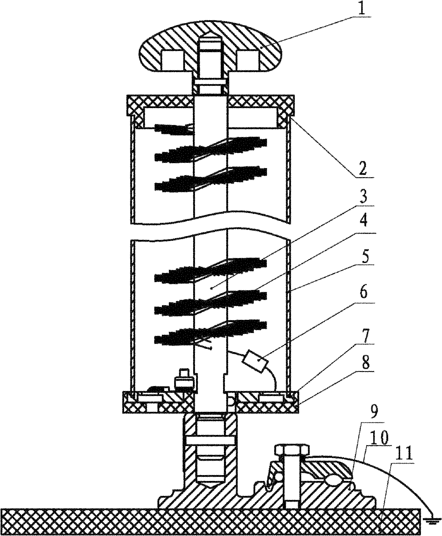
[0021] In this embodiment, the structure of the vehicle protection device is as follows figure 1 As shown, it includes a pin top 1, a conductive support, a discharge brush 4, an induction cylinder 5, a gas discharge tube 6, an upper insulating cover 2, a lower insulating cover 8, a conductive strip 10, a metal washer 7 and an insulating base 11. The conductive support body is made up of cylindrical support rod 3 and base 9, and described support rod 3, base 9 are made of stainless steel, and described support rod 3 is installed on the base 9; Needle top 1 is made of stainless steel, is installed on the support The top of the rod 3; the upper insulating cover 2 and the lower insulating cover 8 are made of nylon, the upper insulating cover 2 is installed on the support rod 3 and is located under the needle top, and the lower insulating cover 8 is installed on the support rod 3 and is located on the upper insulating cover. Next, the metal gasket 7 is installed in the annular groo...

Embodiment 2

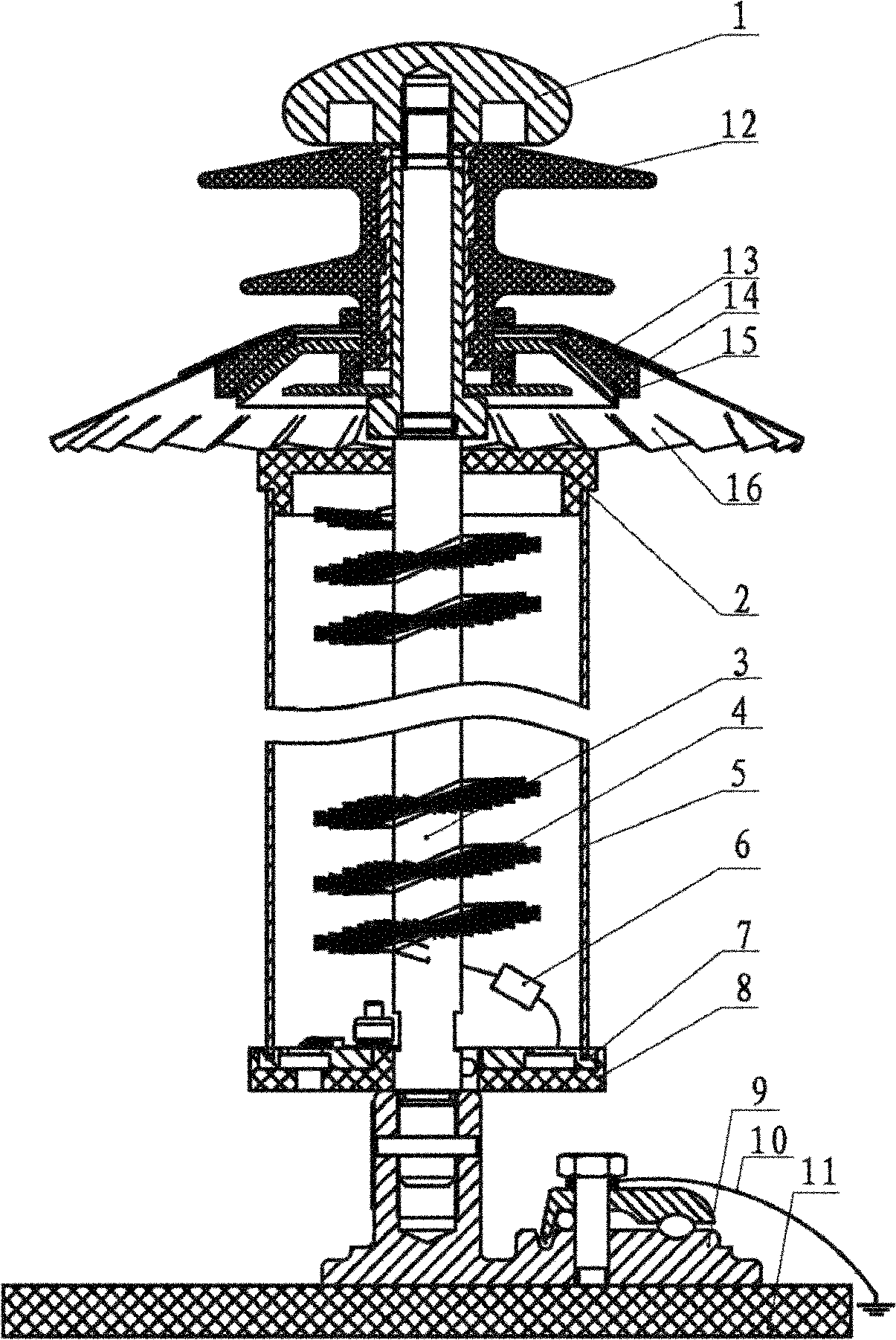
[0023] In this embodiment, the structure of the vehicle protection device is as follows figure 2 shown. The difference from Embodiment 1 is that a bipolar static induction conductor 16 and an insulating bushing 12 are added. The bipolar electrostatic induction conductor 16 is in the shape of a bamboo hat, made of red copper plate or stainless steel plate, and the insulating bushing 12 is made of silicon rubber. The insulating bushing 12 is installed on the cylindrical support rod 3 and is located between the needle top and the upper insulating cover. The bipolar static electricity induction conductor 16 is set on the insulating bushing 12. The upper pressing plate made of red copper plate or stainless steel plate 13 and the lower pressing plate 15 cooperate to realize the fixing on the insulating bushing, and a backing plate 14 made of ceramics is also arranged between the bipolar static electricity induction conductor 16 and the lower pressing plate 15.


PUM


Abstract

The invention relates to a vehicular protection device comprising a conductive strip, a pin ejector, a conductive supporting body, discharging brushes, an induction cylinder, an air discharging tube, an upper insulation cover and a lower insulation cover. The pin ejector is mounted at the top of the conductive supporting body, the upper insulation cover is mounted on the conductive supporting body and arranged below the pin ejector; the lower insulation cover is mounted on the conductive supporting body and arranged below the upper insulation cover; both ends of the induction cylinder are respectively mounted on the upper insulation cover and the lower insulation cover and electrically connected with the conductive supporting body in a transient state through the air discharging tube; thedischarging brushes are mounted along the periphery of the conductive supporting body and arranged in a space encircled by the induction cylinder, the upper insulation cover and the lower insulation cover; and the conductive strip is connected with the conductive supporting body. The vehicular protection device not only has the function of preventing electrostatic accidents, but also has the function of lowering the thunderstrokes probability of mobile facility in thunderstorm weather.

Description

technical field [0001] The invention belongs to protective devices for mobile vehicle-mounted facilities such as oil tank trucks and gas tank trucks, and particularly relates to a vehicle-mounted protective device with the functions of static electricity elimination and lightning protection. Background technique [0002] During the transportation of mobile facilities such as oil tank trucks and gas tank trucks, oil and gas will violently shake, collide, and rub in the tank, which will generate high electrostatic voltage and spark discharge; Under the action of the electrostatic field formed between thunderclouds and the ground, mobile facilities such as oil tankers and gas tankers will face greater static electricity threats. If they are struck by lightning, the consequences will be even more unimaginable. Accidents happen from time to time. In fact, static electricity is not only generated during transportation, but also easily generated during loading and unloading, tank ...

Claims


Application Information

Patent Timeline
Patent Type & Authority Patents(China)
IPC IPC(8): H02H9/06B60R16/06
Inventor 王德言杨国华王俊生涂逊黄贵君杨玉龙
Owner SICHUAN ZHONGGUANG LIGHTNING PROTECTION TECH
Why Eureka
Try Eureka