A liquid spray head, a nozzle plate used for the liquid spray head and a manufacturing method of the nozzle plate

A technology of liquid nozzles and manufacturing methods, which is applied in printing and other directions, and can solve the problems of uncontrollable ink droplet size, inaccurate control of quantum dot film thickness, inconsistent ink droplet size, etc.

Active Publication Date: 2019-02-05
NANJING TECH CORP LTD
View PDF5 Cites 0 Cited by
  • Summary
  • Abstract
  • Description
  • Claims
  • Application Information

AI Technical Summary

Problems solved by technology

However figure 1 The nozzle shown cannot control the size of ink droplets during inkjet printing. This is because the quantum dot solution has two types: hydrophilic and lipophilic, and the nozzle plate is generally made of hydrophilic silicon wafers. When the water-based quantum dot solution is used for inkjet printing, the ink droplet will stick to the nozzle plate at the liquid outlet end of the nozzle port, resulting in a large change in the volume of the ink droplet during the inkjet process, and the ink droplet size is inconsistent, Inhomogeneous volume; even with lipophilic quantum dot solutions for inkjet printing, there are inconsistent sizes of ink droplets
This leads to the inaccurate control of the thickness of the quantum dot film after printing, which makes the resolution of quantum dot light-emitting diodes poor and the product quality low

Method used


Image

  • A liquid spray head, a nozzle plate used for the liquid spray head and a manufacturing method of the nozzle plate
  • A liquid spray head, a nozzle plate used for the liquid spray head and a manufacturing method of the nozzle plate
  • A liquid spray head, a nozzle plate used for the liquid spray head and a manufacturing method of the nozzle plate

Examples


Embodiment 1

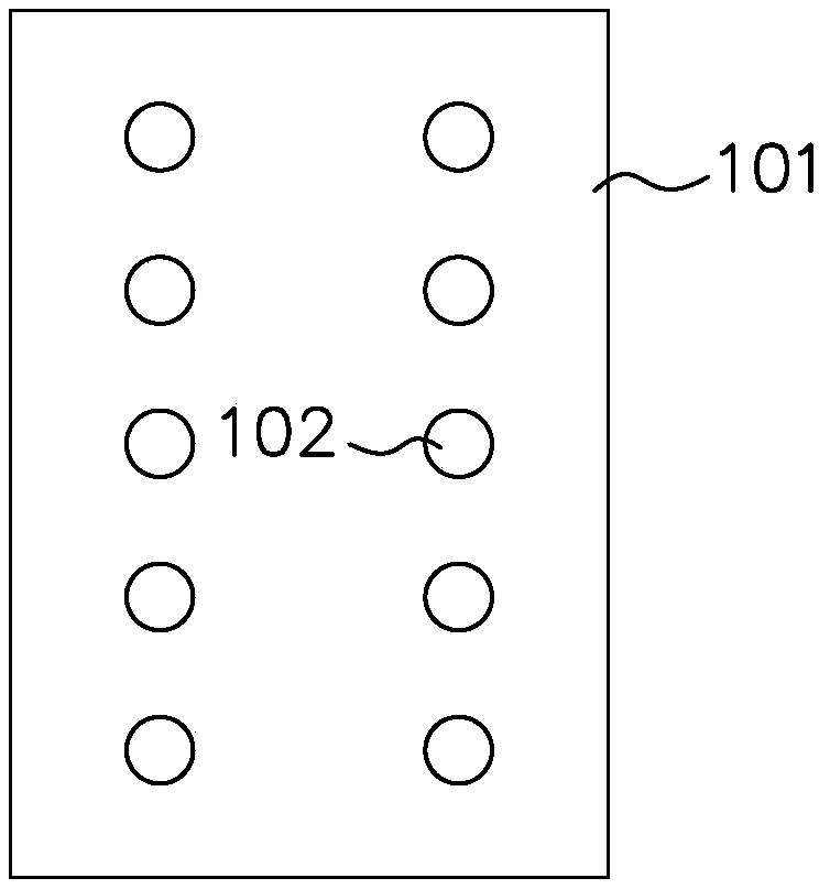
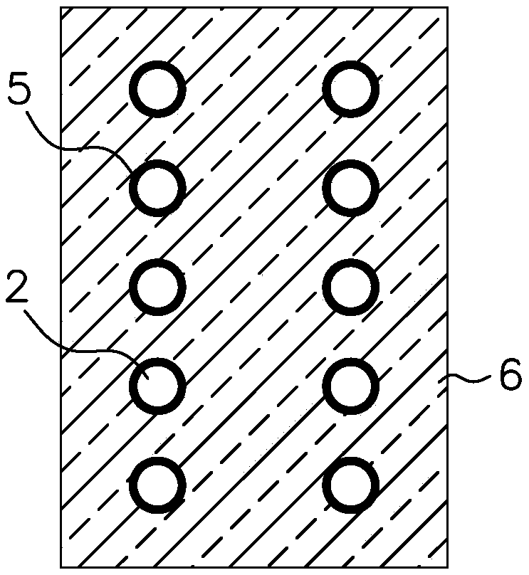
[0088] like figure 2 and image 3 As shown, the present embodiment is used for the nozzle plate of the liquid spray head, including the plate body 1, which is provided with at least one nozzle opening 2; the liquid outlet side of the plate body 1 is provided with a hydrophilic film 3 and a hydrophobic Membrane 4, but at the outer edge of the nozzle opening 2, the hydrophobic membrane 4 does not cover the hydrophilic membrane 3, and the hydrophilic membrane 3 forms a hydrophilic area surface 5 because it is exposed on the outside, and other areas covered by the hydrophobic membrane 4 The surface 6 of the hydrophobic region is then formed.

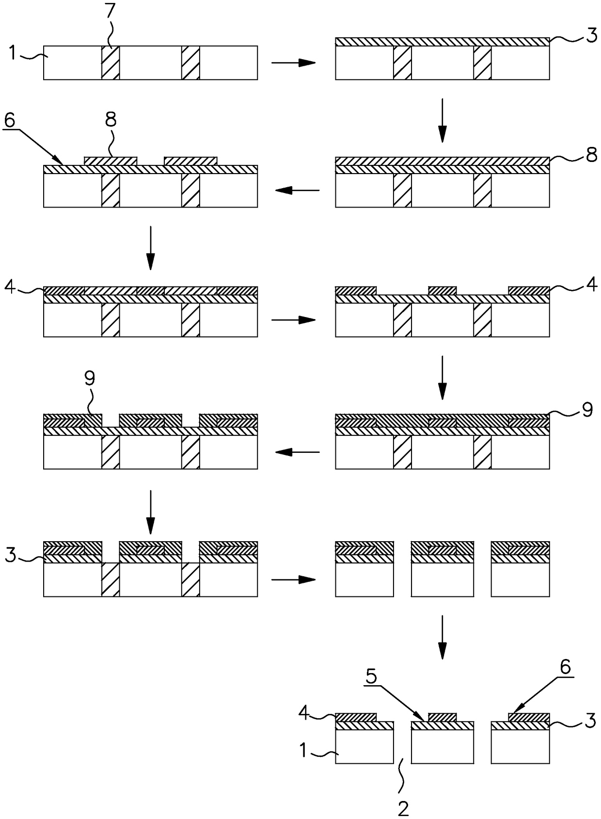
[0089] The manufacture method of above-mentioned nozzle plate comprises the following steps (flow chart as figure 2 ):

[0090] (1) Get a conventional nozzle plate provided with nozzle openings, and fill each nozzle opening with a filler (polysilicon is used in this embodiment);

[0091] (2) Set a hydrophilic film on the liquid outlet ...

Embodiment 2

[0102] like Figure 4 and Figure 5 As shown, the nozzle plate used in this embodiment for the liquid nozzle includes a plate body 1, and at least one nozzle opening 2 is provided on the plate body 1; an oleophilic film 11 and an oleophobic film are sequentially provided on the surface of the plate body on the liquid outlet side. 10, but at the outer edge of the nozzle opening 2, the oleophobic film 10 does not cover the oleophilic film 11, and the oleophilic film 11 forms the surface 12 of the oleophilic area because it is exposed on the outside, and other areas covered by the oleophobic film 10 form a The surface 13 of the oleophobic area; in addition to the surface 12 of the oleophilic area and the surface 13 of the oleophobic area, there is also a blank area 14 on the surface of the plate body on the liquid outlet side.

[0103] The manufacturing method of the above-mentioned nozzle plate comprises the following steps:

[0104] (1) Get a conventional nozzle plate provide...

Embodiment 3

[0117] like Image 6 As shown, the nozzle plate used in this embodiment for the liquid spray head includes a plate body 1, and at least one nozzle opening 2 is provided on the plate body 1; The surface 12 of the lipophilic region on the outer edge, and the surface 13 of the oleophobic region on the periphery of the surface 12 of the lipophilic region, wherein the corresponding position of the surface 12 of the lipophilic region is covered with an oleophilic film 11, and the corresponding position of the surface 13 of the oleophobic region The inside is covered with an oleophobic film 10 , and the thickness of the oleophobic film 10 is greater than the thickness of the oleophilic film 11 .

[0118] The manufacture method of above-mentioned nozzle plate comprises the following steps (its flow chart is as follows Image 6 ):

[0119] (1) Take a conventional nozzle plate provided with nozzle openings, and fill each nozzle opening with a filler (amorphous silicon is used in this ...


PUM


Abstract

The invention discloses a liquid spray head, a nozzle plate used for the liquid spray head and a manufacturing method of the nozzle plate. The nozzle plate for the liquid ejection head includes a plate body, and at least one nozzle opening for ejecting ink is arranged in the plate body, and on the surface of the plate body on the liquid outlet side, a first zone surface and a surrounding first area are arranged around the outer edge of the nozzle opening. The outer edge of the surface of the zone is provided with a surface of the second zone, wherein the lyophilicity of the surface of the first zone is opposite to that of the surface of the second zone, and the lyophilicity of the surface of the first zone is the same as that of the ink. In the present invention, the surface of the first area on the nozzle plate that is closer to the nozzle opening is set to have the same lyophilicity as the quantum dot solution, and the surface of the second area on the nozzle plate that is farther away from the nozzle opening is set to have the same lyophilicity as the quantum dot solution. The lyophilicity is opposite. In this way, by changing the surface tension of ink droplets in contact with different parts of the nozzle plate during the inkjet printing process, accurate control of the ejected size of ink droplets can be achieved.

Description

technical field [0001] The invention relates to a liquid spray head, in particular to a liquid spray head, a nozzle plate used for the liquid spray head and a manufacturing method of the nozzle plate. Background technique [0002] Quantum dots are nanomaterials composed of a limited number of atoms, and the three dimensions of the atoms are all on the order of nanometers. Due to its quantum size effect, the half-peak width of quantum dots is very narrow, so it also has excellent color purity. Making quantum dot materials into quantum dot light-emitting diodes (Quantum Dot Light Emitting Diode, referred to as QLED) can achieve ratio An electromechanical light-emitting diode (Organic Light-Emitting Diode, OLED for short) display device has a better color gamut. [0003] A general quantum dot light-emitting diode device includes the following parts, respectively a base substrate, and an anode, a hole transport layer, a light-emitting layer, an electron transport layer and a ca...

Claims


Application Information

Patent Timeline
Patent Type & Authority Patents(China)
IPC IPC(8): B41J2/14B41J2/16
CPCB41J2/14B41J2/16B41J2/1606
Inventor 田庆海
Owner NANJING TECH CORP LTD
Why Eureka
Try Eureka