Return force power generation device

A technology of generating sets and return springs, applied in the direction of electromechanical devices, electrical components, electric components, etc., can solve problems such as uneven water flow, turbine impact, turbine damage, etc., to avoid unlimited tilt, reduce impact pressure, and flexibly rotate The effect of the characteristic

Pending Publication Date: 2018-02-02
ZHUZHOU SOUTHERN VALVE
View PDF0 Cites 0 Cited by
  • Summary
  • Abstract
  • Description
  • Claims
  • Application Information

AI Technical Summary

Problems solved by technology

[0003] In the case of hydropower generation, the traditional hydropower technology mainly uses the force of the fluid to directly drive the turbine to rotate, thereby driving the electromagnetic induction generator to generate electricity. However, the turbine is not specifically designe

Method used


Image

  • Return force power generation device
  • Return force power generation device
  • Return force power generation device

Examples


Embodiment

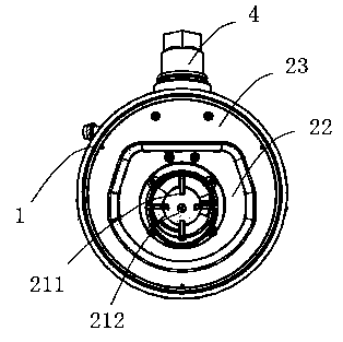
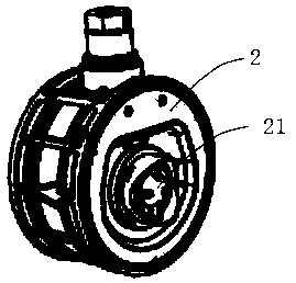
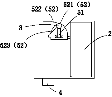
[0022] Such as Figure 1~4 As shown, a pull-back power generation device includes a device casing 1 with connecting through holes at both ends, a generator set 2 located in the device casing 1, a fixed shaft 3 fixed on the device casing 1, and can support the generator set 2 relative to the fixed The swing mechanism for vertically swinging the axis of the shaft 3 also includes a battery assembly 4 arranged outside the device casing 1 .

[0023] The generator set 2 includes a power generation core 21, a first flow surface 22 arranged on the outer periphery of the power generation core 21, and a second flow surface 23 connecting the outer periphery of the first flow surface 22 with the inner periphery of the connecting through hole at one end of the device casing 1. , the power generation core 21 is electrically connected to the battery assembly 4 .

[0024] The orientation of the fixed shaft 3 is such that when the generator set 2 swings to the lowest position, the first flow ...


PUM


Abstract

The invention belongs to the technical field of power generation devices, and discloses a regenerative power generation device, comprising a device casing with connecting through holes at both ends, a generator set located in the device casing, a fixed shaft fixed on the device casing, which can support the generator set relative to the fixed The swing mechanism swings vertically in the direction of the shaft axis, and also includes a battery assembly arranged outside the device casing; the generator set includes a power generation core, a first flow surface arranged on the outer periphery of the power generation core, and the outer circumference of the first flow surface is connected with the power generation core. One end of the device shell is connected to the second flow surface of the inner circumference of the through hole, and the power generation core is electrically connected to the battery assembly; the fixed shaft is arranged in such a way that when the generator set swings to the lowest position, the first flow surface is connected to the device shell. The connecting through holes at both ends are parallel. The setting of the swing mechanism provides effective support for the swing of the generator set, stabilizes the medium flow at the power generation core, and makes the generator set generate electricity evenly.

Description

technical field [0001] The present invention relates to the technical field of power generation devices, in particular to a pull-back power generation device. Background technique [0002] With the increasing shortage of energy, people began to study how to make full use of energy and improve the utilization rate of energy. Flow energy in the form of renewable energy, wind energy, and water flow is a ubiquitous renewable resource. [0003] In the case of hydropower generation, the traditional hydropower technology mainly uses the fluid force to directly drive the turbine to rotate, thereby driving the electromagnetic induction generator to generate electricity. However, the turbine is not specifically designed for the flow of water flow, that is, the water flow is large. At the same time, due to the uneven water flow, the electromagnetic induction generator will not generate electricity when it flows through the turbine, which will directly affect the service life of its rec...

Claims


Application Information

Patent Timeline
IPC IPC(8): H02K7/18F03B13/00
CPCH02K7/1823F03B13/00
Inventor 黄靖谢爱华唐金鹏
Owner ZHUZHOU SOUTHERN VALVE
Why Eureka
Try Eureka