An intelligent pressure reducing valve integrating power generation and data acquisition functions
A data acquisition and pressure reducing valve technology, applied in valve details, valve devices, engine components, etc., can solve problems such as troublesome maintenance, affecting the service life of rechargeable batteries, uneven water flow, etc.
- Summary
- Abstract
- Description
- Claims
- Application Information
AI Technical Summary
Problems solved by technology
Method used
Image
Examples
Embodiment 1
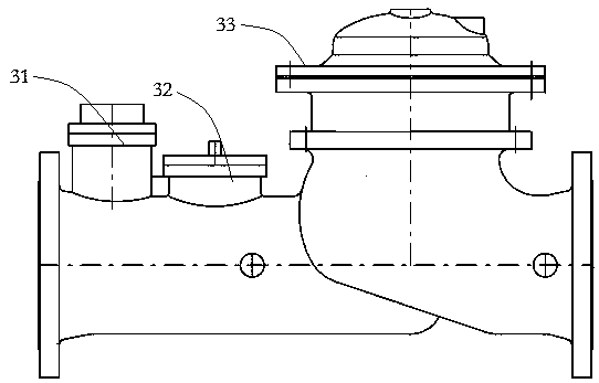
[0031] like figure 1 As shown, this embodiment provides an intelligent pressure reducing valve that integrates power generation and data acquisition functions. This embodiment takes a T-type pressure reducing valve as an example. The intelligent pressure reducing valve includes a pressure reducing valve body 33, a power generating device 32, a data acquisition component and a display terminal.
[0032]The data acquisition components include flow meters, pressure sensors, and water quality sensors; in the specific implementation process, other types of data acquisition components can also be used according to specific requirements, such as collecting the opening of the valve body and the temperature of the fluid. In this embodiment, the flowmeter adopts an ultrasonic flowmeter 31 that can measure the consumption of the pipe network and has a temperature compensation function at the same time. One pressure sensor is provided before and one after the valve body 33 of the pressu...
Embodiment 2
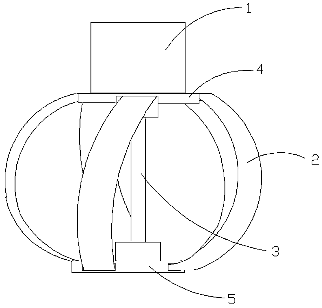
[0046] like Figure 4 , Figure 5 , Image 6 As shown, the difference between this embodiment and Embodiment 1 is that the intelligent pressure reducing valve of this embodiment is a Y-type intelligent pressure reducing valve; the power generating device 32 further includes a swing mechanism; perpendicular to the fluid direction. There is a guide seat 13 for guiding the fluid at the inlet of the pressure reducing valve. The outer circumference of the guide seat is bolted to the inner wall of the valve. A conical guide surface and a cylindrical guide surface are arranged in the guide seat. It flows through the conical guide surface, the cylindrical guide surface and the power generating assembly in sequence, and the diameter of the cylindrical guide surface is adapted to the size of the runner.
[0047] like Image 6 As shown, the power generation assembly 9 is placed inside the pipeline, and also includes a swing mechanism that can support the power generation assembly 9 t...
Embodiment 3
[0054] like Figure 7 As shown, the difference between this embodiment and Embodiment 1 or Embodiment 2 is that a small runner 8 is provided inside the runner 2; the structure of the small runner 8 is the same as that of the runner 2; Wheel 2 blade positions are staggered. Lightweight materials can be selected for the material of the small runner to achieve the lightweight of power generation components.
[0055] When the fluid flow is constant and the flow rate is normal, the small runner and the large runner rotate under the impact of the fluid, thereby driving the rotating shaft 3 to rotate. The small runner increases the contact surface with the fluid so as to increase the thrust of the fluid on the blades and increase the rotation speed of the main shaft 3 . When the fluid flow decreases and the flow velocity decreases, the small runner 8 and the blades of the runner 2 are staggered, and the water flowing through the runner 2 will flow through the small runner, which im...
PUM
 Abstract
Description
Claims
Application Information
 - R&D
- Intellectual Property
- Life Sciences
- Materials
- Tech Scout
- Unparalleled Data Quality
- Higher Quality Content
- 60% Fewer Hallucinations
Browse by: Latest US Patents, China's latest patents, Technical Efficacy Thesaurus, Application Domain, Technology Topic, Popular Technical Reports.
© 2025 PatSnap. All rights reserved.Legal|Privacy policy|Modern Slavery Act Transparency Statement|Sitemap|About US| Contact US: help@patsnap.com


