
Stirring type filter

A filter and stirring technology, which is applied in the field of chemical raw material processing, can solve the problems affecting the performance of modified asphalt, the quality of modified asphalt, and the performance of raw materials, so as to improve the quality and performance, and facilitate maintenance and cleaning , Improve the effect of maintenance efficiency

Pending Publication Date: 2018-02-06
武汉市三维纵横机电设备有限公司
View PDF7 Cites 6 Cited by
  • Summary
  • Abstract
  • Description
  • Claims
  • Application Information

AI Technical Summary

Problems solved by technology

[0002] At present, many chemical raw materials have particles whose particle size exceeds the set standard. These particles will affect the product quality of raw materials, thereby affecting the performance of raw materials.
Due to the existence of particulate matter, the use of conventional stirring devices has been unable to mix the raw materials evenly
For example, the raw material of waterproof membrane - modified asphalt is mixed with external additives (modifiers) such as rubber, resin, high molecular polymer, ground rubber powder or other fillers, or lightly oxidized asphalt, etc. Measures to improve the performance of asphalt or asphalt mixture and make asphalt binder. During the modification of asphalt, some rubber powder, SBS, SBR, and other materials will not be completely melted, resulting in the finished modified asphalt. There are a lot of particles, and the modified asphalt mixture is a high-viscosity, heterogeneous fluid. It is difficult to mix the asphalt mixture evenly with the usual stirring device, which seriously affects the quality of the modified asphalt, thus affecting the performance of the modified asphalt

Method used


Image

  • Stirring type filter
  • Stirring type filter
  • Stirring type filter

Examples


Embodiment Construction

[0031] The principles and features of the present invention are described below in conjunction with the accompanying drawings, and the examples given are only used to explain the present invention, and are not intended to limit the scope of the present invention.

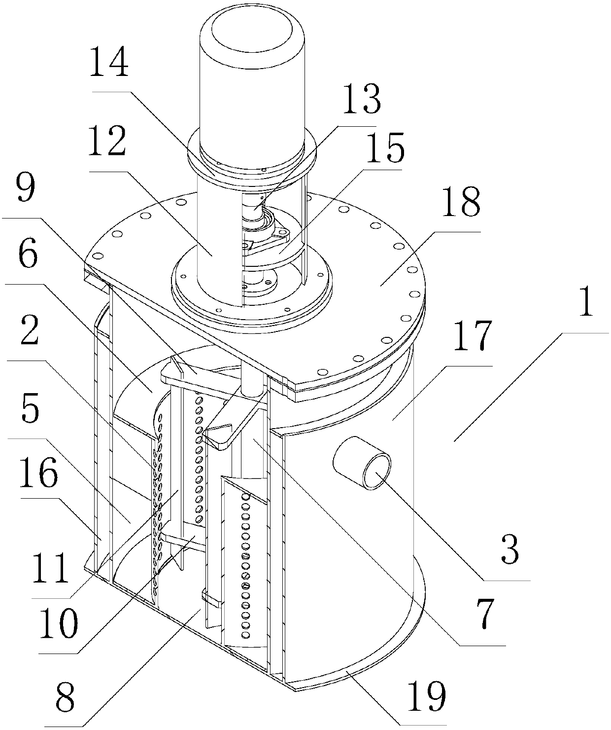
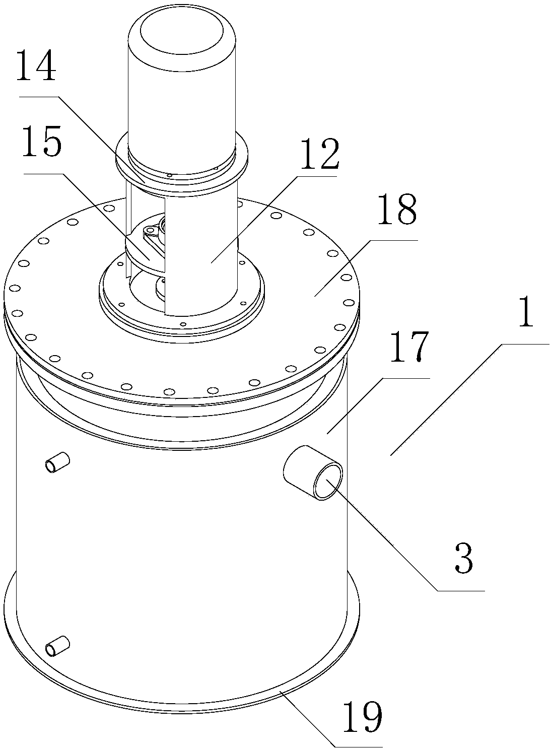
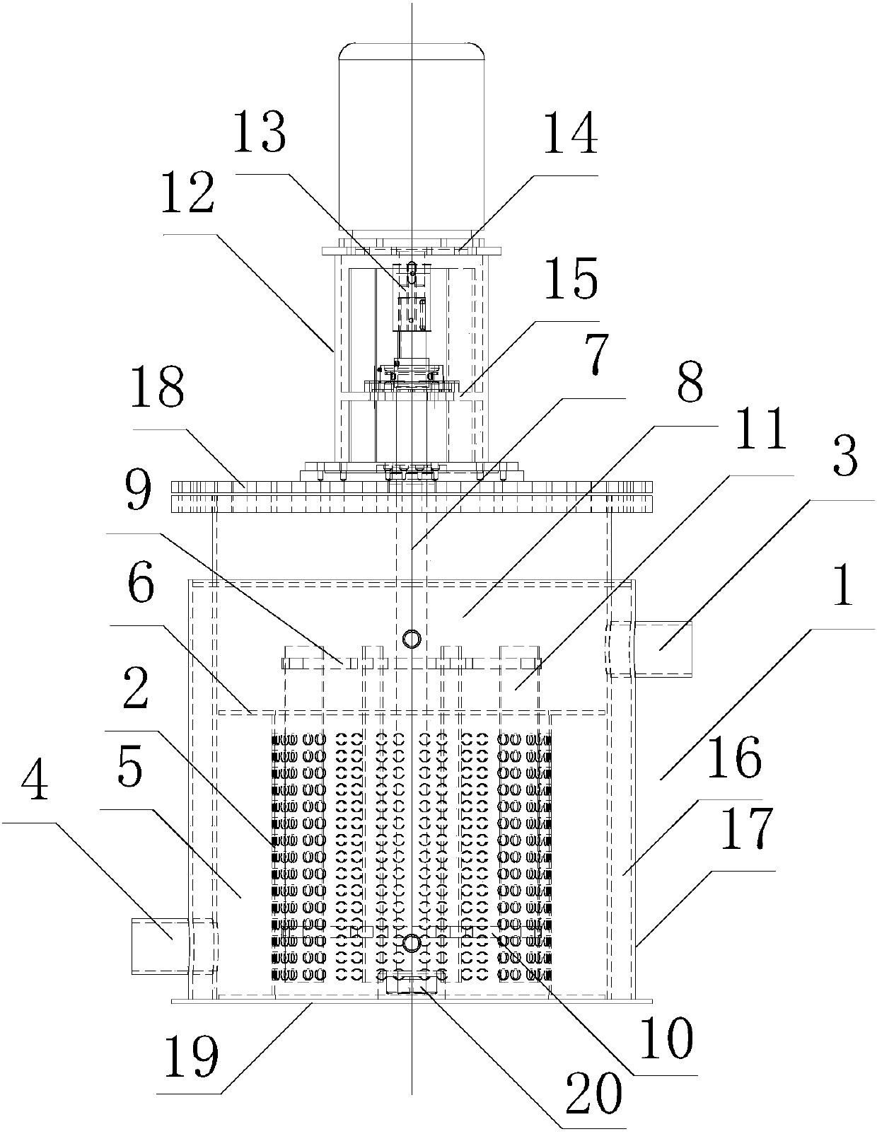
[0032] Such as Figures 1 to 3 As shown, a stirring filter includes an outer cylinder 1, a driving device, a stirring device and a filter cartridge 2, the upper and lower ends of the outer cylinder 1 are closed, and the upper side wall of the outer cylinder 1 is provided with There is a feed port 3, and the lower part of the side wall of the outer cylinder 1 is provided with a discharge port 4; the filter cartridge 2 is arranged in the outer cylinder 1, and the height of the feed port 3 is not lower than The upper end of the filter cartridge 2, the height of the discharge port 4 is not higher than the upper end of the filter cartridge 2, the upper and lower ends of the filter cartridge 2 are open, and the side wall ...


PUM


Abstract

The invention relates to a stirring type filter. The stirring type filter comprises an outer cylinder, a driving device, a stirring device and a filtering cylinder, wherein the upper part of the sidewall of the outer cylinder is provided with a material inlet, and the lower part of the side wall of the outer cylinder is provided with a material outlet; the filtering cylinder is arranged in the outer cylinder, the height of the material inlet is not lower than the upper end of the filtering cylinder, a plurality of filtering holes are formed in the side wall of the filtering cylinder, and thestirring device is vertically arranged in the outer cylinder and is also positioned in the filtering cylinder; a material filtering cavity is formed between the filtering cylinder and the side wall ofthe outer cylinder; the upper end of the stirring device extends up out of the outer cylinder; the driving device is arranged at the upper end of the outer cylinder; the output end of the driving device is in transmission connection with the upper end of the stirring device, and the driving device is used for driving the stirring device to rotate. The stirring type filter has the advantages thatthe raw material is stirred by the stirring device, so that the material can be uniformly mixed; the raw material can be filtered by the filtering cylinder in the stirring process, and then the particulate matters in the raw material can be separated, so as to ensure the quality of raw material which is discharged out of the material outlet.

Description

technical field [0001] The invention relates to the technical field of chemical raw material processing, in particular to a stirring filter. Background technique [0002] At present, many chemical raw materials have particles whose particle size exceeds the set standard, and these particles will affect the product quality of the raw materials, thereby affecting the performance of the raw materials. Due to the existence of particles, the conventional stirring device can no longer mix the raw materials evenly. For example, the raw material of waterproof membrane - modified asphalt is mixed with external additives (modifiers) such as rubber, resin, high molecular polymer, ground rubber powder or other fillers, or lightly oxidized asphalt, etc. Measures to improve the performance of asphalt or asphalt mixture and make asphalt binder. During the modification of asphalt, some rubber powder, SBS, SBR, and other materials will not be completely melted, resulting in the finished mod...

Claims


Application Information

Patent Timeline
IPC IPC(8): B01D29/11B01D29/86B01D35/18
CPCB01D29/117B01D29/86B01D35/18
Inventor 潘艳芳杨杰杨翩熊豪
Owner 武汉市三维纵横机电设备有限公司
Learn More