Novel efficient automobile cleaning device

A cleaning device and high-efficiency technology, which can be applied in the direction of vehicle exterior cleaning devices, etc., can solve the problems of low car washing efficiency and high labor intensity of personnel.

Inactive Publication Date: 2018-02-06
施佳云
View PDF8 Cites 3 Cited by
  • Summary
  • Abstract
  • Description
  • Claims
  • Application Information

AI Technical Summary

Problems solved by technology

[0006] In order to overcome the shortcomings of the existing car washing device that car washers use manual car washing, the car washing efficiency is low and the labor intensity of personnel is high, the technical problem to be solved by the invention is to provide a new type of high-efficiency car washing device

Method used


Image

  • Novel efficient automobile cleaning device
  • Novel efficient automobile cleaning device
  • Novel efficient automobile cleaning device

Examples


Embodiment 1

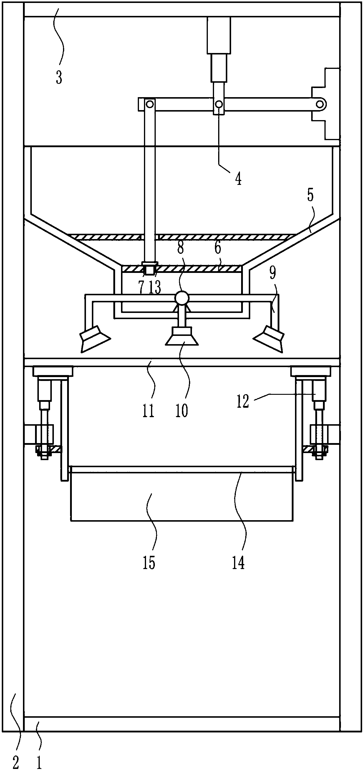
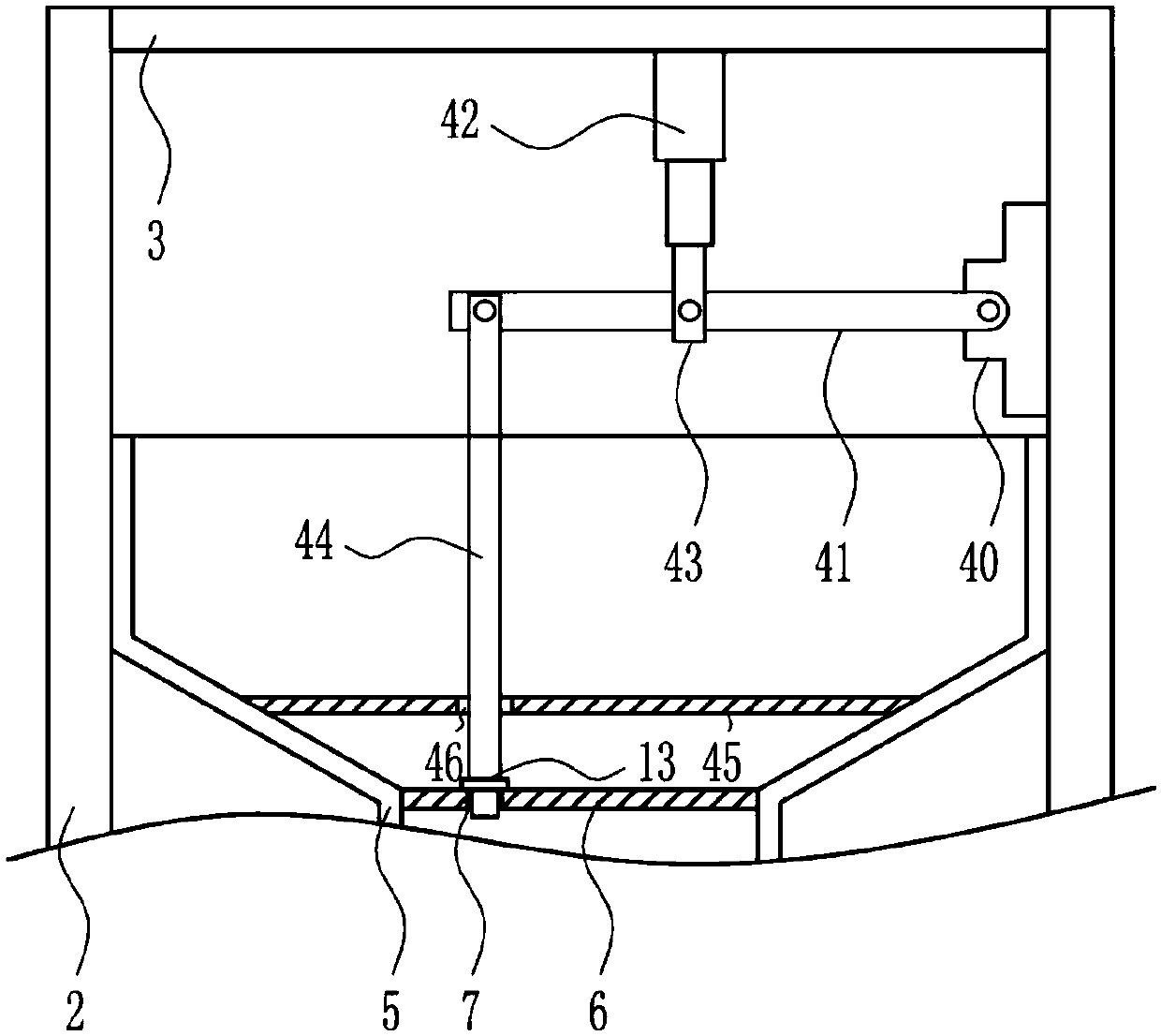
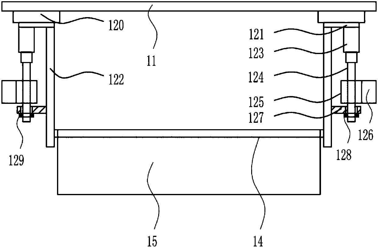
[0035] A new type of high-efficiency car cleaning device, such as Figure 1-7 As shown, it includes a bottom plate 1, a support rod 2, a top plate 3, a switch water mechanism 4, a water tank 5, a baffle plate 6, a water pump 8, a hard pipe 9, a nozzle 10, a support plate 11, a moving mechanism 12, a rubber stopper 13, Cross bar 14 and the first towel 15, bottom plate 1 left and right ends are all provided with support bar 2, upper end is provided with top plate 3 between the support bar 2 of left and right sides, top plate 3 bottom right side is provided with switch water mechanism 4, left and right sides A water tank 5 is arranged on the upper side between the square support rods 2, and the water tank 5 is located below the switch water mechanism 4. A baffle plate 6 is provided on the inner lower side of the water tank 5, and a second through hole 7 is opened on the left side of the baffle plate 6. A rubber stopper 13 is placed in the hole 7, the bottom of the switch water me...

Embodiment 2

[0037] A new type of high-efficiency car cleaning device, such as Figure 1-7 As shown, it includes a bottom plate 1, a support rod 2, a top plate 3, a switch water mechanism 4, a water tank 5, a baffle plate 6, a water pump 8, a hard pipe 9, a nozzle 10, a support plate 11, a moving mechanism 12, a rubber stopper 13, Cross bar 14 and the first towel 15, bottom plate 1 left and right ends are all provided with support bar 2, upper end is provided with top plate 3 between the support bar 2 of left and right sides, top plate 3 bottom right side is provided with switch water mechanism 4, left and right sides A water tank 5 is arranged on the upper side between the square support rods 2, and the water tank 5 is located below the switch water mechanism 4. A baffle plate 6 is provided on the inner lower side of the water tank 5, and a second through hole 7 is opened on the left side of the baffle plate 6. A rubber stopper 13 is placed in the hole 7, the bottom of the switch water me...

Embodiment 3

[0040] A new type of high-efficiency car cleaning device, such as Figure 1-7 As shown, it includes a bottom plate 1, a support rod 2, a top plate 3, a switch water mechanism 4, a water tank 5, a baffle plate 6, a water pump 8, a hard pipe 9, a nozzle 10, a support plate 11, a moving mechanism 12, a rubber stopper 13, Cross bar 14 and the first towel 15, bottom plate 1 left and right ends are all provided with support bar 2, upper end is provided with top plate 3 between the support bar 2 of left and right sides, top plate 3 bottom right side is provided with switch water mechanism 4, left and right sides A water tank 5 is arranged on the upper side between the square support rods 2, and the water tank 5 is located below the switch water mechanism 4. A baffle plate 6 is provided on the inner lower side of the water tank 5, and a second through hole 7 is opened on the left side of the baffle plate 6. A rubber stopper 13 is placed in the hole 7, the bottom of the switch water me...


PUM


Abstract

The invention relates to a cleaning device, in particular to a novel efficient automobile cleaning device. For solving the technical problem, the novel efficient automobile cleaning device comprises abase plate, supporting rods, a top plate, a water switch mechanism, a water tank, a baffle, a water pump and the like. The supporting rods are arranged at the left end and the right end of the base plate, the top plate is arranged at the upper end between the supporting rods on the left side and the right side, the water switch mechanism is arranged on the right side of the bottom of the top plate, the water tank is arranged on the upper side between the supporting rods on the left side and the right side and is located below the water switch mechanism, the baffle is arranged on the lower side in the water tank, a second through hole is formed in the left side of the baffle, and a rubber plug is arranged in the second through hole. The novel efficient automobile cleaning device has the advantages of being capable of automatically cleaning automobiles, high in automobile cleaning efficiency and reducing the labor intensity of automobile cleaning workers, and automobile washers can control the device to perform automatic automobile cleaning only by needing a start switch through the water switch mechanism and a moving mechanism.

Description

technical field [0001] The invention relates to a cleaning device, in particular to a novel high-efficiency car cleaning device. Background technique [0002] Cleaning is a method of using a chemical agent to remove dirt on the surface of an object. It uses the surface pollutants or coatings of the cleaning agent to chemically transform, dissolve, and peel off to achieve the effects of degreasing, rust removal, and decontamination. [0003] Car cleaning refers to the cleaning of the appearance of the car. It is a problem that every car owner or driver often faces. In recent years, car wash shops have gradually become a hot investment project in many large and medium-sized cities. Important precautions for cleaning, car cleaning can play a very good maintenance effect on the car. [0004] Car cleaning is favored by many car lovers because of its low cost and simple operation. The existing car cleaning devices have the disadvantages that car washers use manual car washing, lo...

Claims


Application Information

Patent Timeline
Patent Type & Authority Applications(China)
IPC IPC(8): B60S3/04
CPCB60S3/04
Inventor 施佳云甘磊林嘉琳
Owner 施佳云
Why Eureka
Try Eureka