Manufacturing method of motorcycle accessory

A manufacturing method and motorcycle technology, applied in the field of pipe fittings manufacturing, can solve problems such as easy surface wear, and achieve the effect of improving efficiency

Active Publication Date: 2018-03-06
重庆博创知识产权运营有限公司
View PDF1 Cites 0 Cited by
  • Summary
  • Abstract
  • Description
  • Claims
  • Application Information

AI Technical Summary

Problems solved by technology

[0003] The present invention intends to provide a method for manufacturing motorcycle accessories to solve the problem that the surface of the pipe fittings is easy to wear during the cleaning process

Method used


Image

  • Manufacturing method of motorcycle accessory
  • Manufacturing method of motorcycle accessory

Examples


Embodiment Construction

[0018] Further detailed explanation through specific implementation mode below:

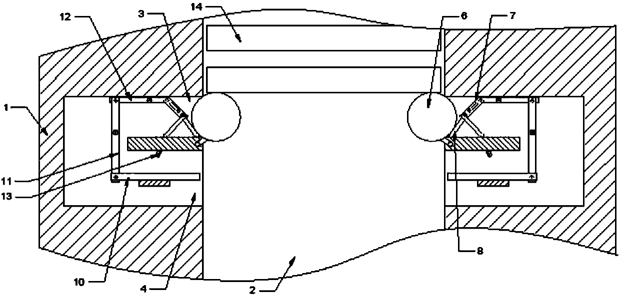
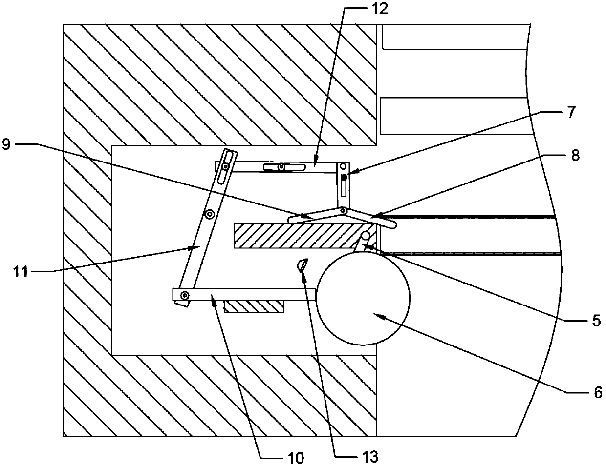
[0019] The reference signs in the drawings of the description include: frame 1, transmission channel 2, first control channel 3, second control channel 4, swing shaft 5, control ball 6, slide bar 7, first connecting rod 8, second Connecting rod 9, drive rod 10, swing rod 11, control rod 12, sucker 13, pipe fitting 14.

[0020] The embodiment is basically as attached figure 1 , figure 2 Shown: the manufacturing method of motorcycle accessory, comprises the following steps:

[0021] Step 1: prepare a frame, set the transmission channel 2 along the vertical direction of the frame, the width of the transmission channel 2 is slightly larger than the length of the pipe fitting 14, and the two sides of the transmission channel 2 are respectively equipped with control units, the control unit includes two horizontal The first control channel 3 and the second control channel 4 are set, the cross-sectio...


PUM


Abstract

The invention relates to the field of machining, in particular to a manufacturing method of a motorcycle accessory. A conveying channel is vertically arranged on a machine frame, control units are installed on the two side walls of the conveying channel, a pipe is supported and fixed in the mode that a first connection rod stretches into inner holes in the two ends of the pipe, and therefore the outer surface of the pipe is completely exposed outside. On one hand, it is ensured that a dust collection device carries out all-directional dust collection on the pipe. On the other hand, the problemthat surface abrasion is caused due to friction between two pipes is avoided.

Description

technical field [0001] The invention relates to the field of mechanical processing, in particular to a method for manufacturing a pipe fitting. Background technique [0002] Pipe fittings usually play the role of support and connection in the motorcycle machine. Since the pipe fittings will adhere to dust during processing or transmission, the surface of the pipe fittings needs to be cleaned before packaging. In the existing cleaning technology, the pipe fittings are usually arranged on the conveyor belt, and the pipe fittings are transported to the cleaning mechanism by the conveyor belt. , but the problem with this cleaning method is that the part of the pipe fittings in contact with the conveyor belt is not clean. Therefore, in order to solve the above problems, a driving mechanism that drives the pipe fittings to roll back and forth on the conveyor belt is added in the prior art, so that the cleaning mechanism has no effect on the pipe fittings. However, the problem wit...

Claims


Application Information

Patent Timeline
IPC IPC(8): B08B9/023B08B13/00
CPCB08B9/023B08B13/00
Inventor 曾义杰
Owner 重庆博创知识产权运营有限公司
Why Eureka
Try Eureka