Clutch devices

A clutch device and clutch technology, applied in the direction of clutches, friction clutches, mechanically driven clutches, etc., can solve problems such as inability to prevent wandering and inability to maintain

Active Publication Date: 2018-02-06
SCHAEFFLER TECH AG & CO KG
View PDF4 Cites 0 Cited by
  • Summary
  • Abstract
  • Description
  • Claims
  • Application Information

AI Technical Summary

Problems solved by technology

[0003] However, it is necessary for effective unbalance compensation that the individual components assume a defined relative position to one another and that this relative position is maintained over the overall operation of the clutch device, since otherwise "playing" cannot be prevented, so that the setting is adjusted in the assembled state. The unbalance compensation cannot be maintained at runtime

Method used


Image

  • Clutch devices
  • Clutch devices
  • Clutch devices

Examples


Embodiment Construction

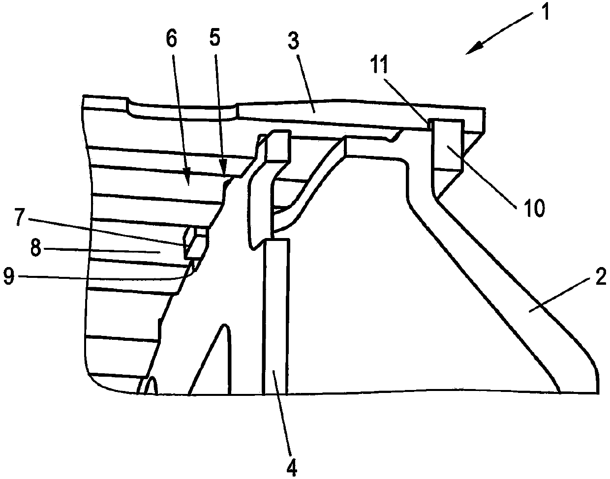
[0030] figure 1 A clutch device 1 is shown, comprising a clutch cover 2 and an outer clutch plate carrier 3 . The outer clutch plate (not shown) is assigned to the outer clutch plate carrier 3 and forms a clutch plate pack with the inner clutch plate (not shown) of the inner clutch plate carrier. Furthermore, a spring support element 4 is formed which has a toothing 5 which cooperates with a toothing 6 of the outer clutch carrier 3 . According to this embodiment, the clutch cover 2 has a first connecting element 7 which fits into a second connecting element 8 of the outer clutch plate carrier 3 . According to figure 1 In the exemplary embodiment shown in , the first connecting element 7 is formed integrally with the clutch cover 2 as a finger protruding from the clutch cover. The second connecting element 8 of the outer clutch carrier is formed by the toothing 6 of the outer clutch carrier. The first connecting element 7 of the clutch cover 2 fits into a corresponding toot...


PUM


Abstract

The invention discloses clutch devices (1, 15, 19, 20). Each clutch device comprises a clutch cover (2), and at least one clutch disc group composed of an outer clutch disc (16) belonging to an outerclutch disc support (3) and an inner clutch disc (17) belonging to an inner clutch disc support. The clutch cover (2) and the outer clutch disc support (3) surround the same rotary axis. The outer clutch disc support (3) and the clutch cover (2) are connected in an anti-torsional manner.

Description

technical field [0001] The invention relates to a clutch device, comprising a clutch cover and at least one clutch disc pack, the clutch disc pack consisting of an outer clutch disc associated with an outer clutch disc carrier and an inner clutch disc associated with an inner clutch disc carrier, wherein the clutch cover and the outer clutch plate carrier are arranged about a common axis of rotation. Background technique [0002] Such clutch devices are known from the prior art and are used in motor vehicles, for example, as multi-plate clutches, in particular as double clutches. It is known here that between the clutch cover, the outer clutch plate carrier and, if present, a spring support element, for example a spring support plate, friction can occur between the individual components due to a rotational movement about a common rotational axis of the clutch arrangement. relative movement. This is particularly disadvantageous in that due to the relative movement there is ...

Claims


Application Information

Patent Timeline
Patent Type & Authority Applications(China)
IPC IPC(8): F16D13/58F16D13/64
CPCF16D13/58F16D13/648F16D2300/22F16D2300/26F16D13/52F16D13/683
Inventor O·诺尔P·泰珀
Owner SCHAEFFLER TECH AG & CO KG
Why Eureka
Try Eureka