Integrated air nozzle
A nozzle and casing technology, applied in the field of integrated nozzles, can solve problems such as the inability to adjust the air collection effect according to needs, the bulky volume of split nozzles, and increase the difficulty of use by consumers, so as to improve the user experience and strengthen Strength, avoiding the effect of inconvenient operation
- Summary
- Abstract
- Description
- Claims
- Application Information
AI Technical Summary
Problems solved by technology
Method used
Image
Examples
Embodiment 1
[0055] Embodiment 1, this embodiment is an integrated tuyere.
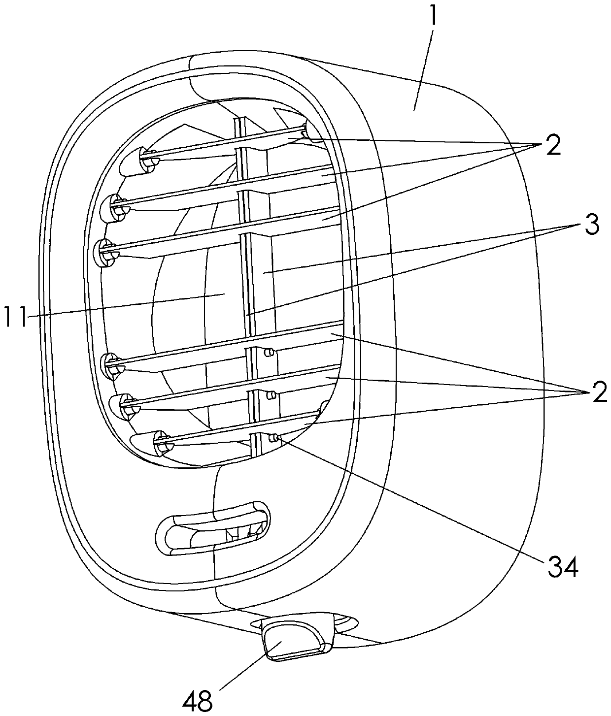
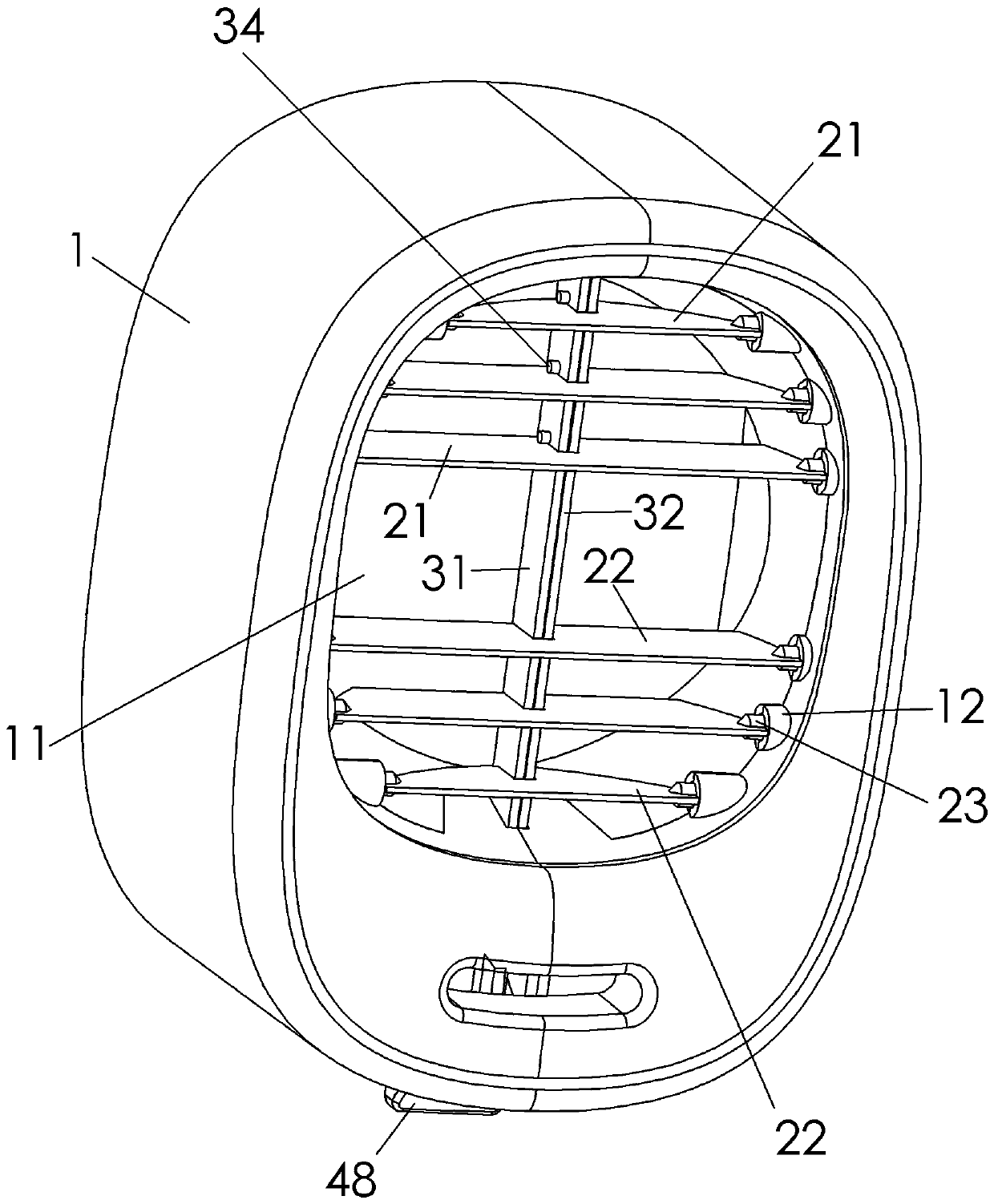
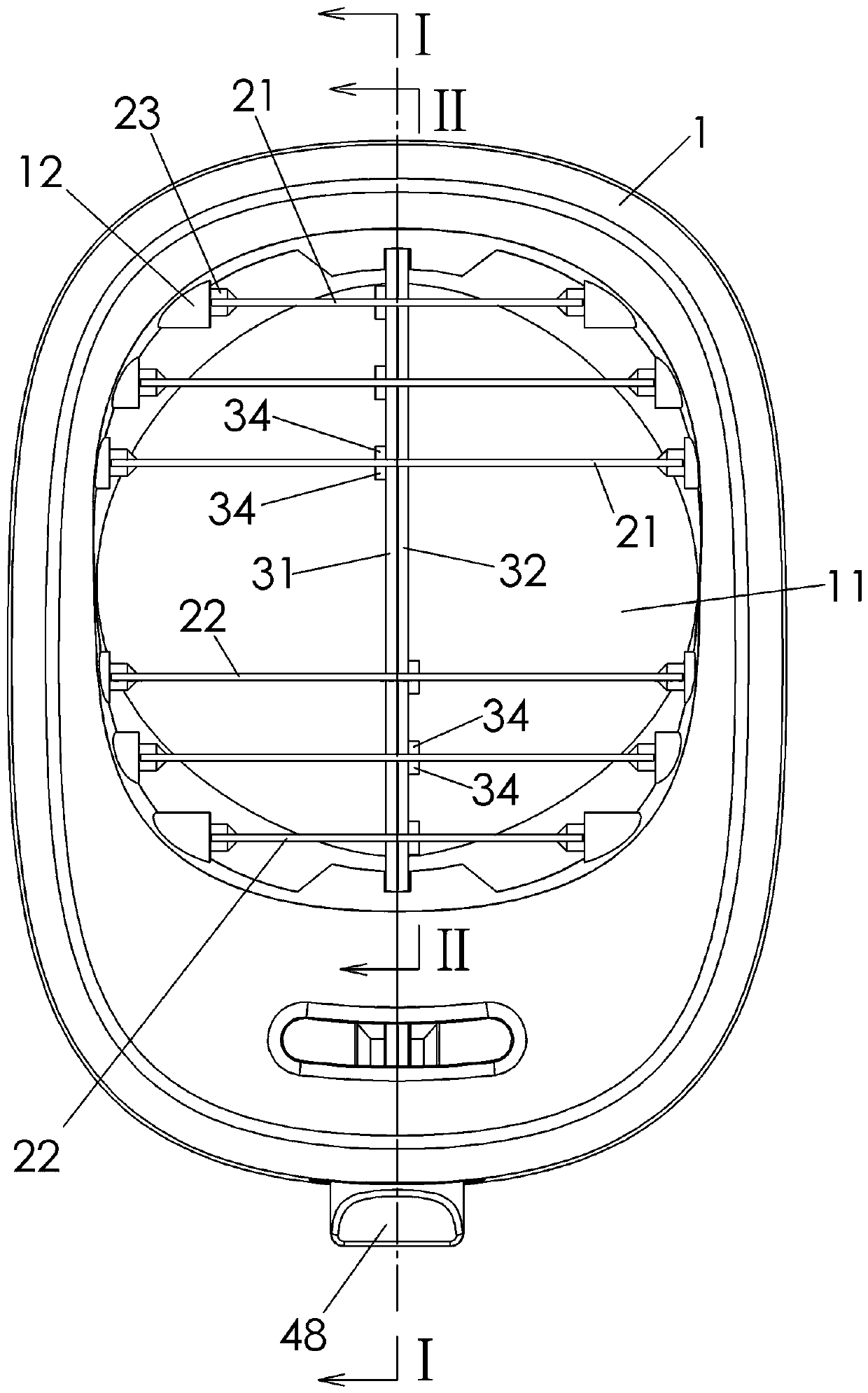
[0056] see Figure 1-Figure 11 ; An integrated air nozzle, which includes a housing 1 provided with an air outlet 11 and a connecting rod limiting groove 15 , an air guide vane 2 , a connecting rod 3 , and a gear position member 4 .
[0057] The wind guide vane 2 is rotatably arranged in the air outlet 11 . For example, both ends of the air guide vane 2 are provided with hinged posts 23, and the inner wall of the air outlet 11 is provided with a hinged seat 12, and the hinged posts 23 are inserted into the hinged seat 12, so that the air guide vane 2 is rotatably arranged in the air outlet 11 .
[0058] The air guide vanes 2 include three upper air guide vanes 21 and three lower air guide vanes 22 . Certainly, there may be only one upper air guide vane 21 and only one lower air guide vane 22 .
[0059] The connecting rod 3 includes an upper connecting rod 31 and a lower connecting rod 32 , and both the upper c...
Embodiment 2
[0076] Embodiment 2, this embodiment is an integrated tuyere.
[0077] Such as Figure 12 As shown, the difference between this embodiment and the first embodiment lies in the steering block 34 .
[0078]The section of the steering block 34 of the present embodiment (as Figure 12 As shown, the cross-section of the steering block 34 taken by the II-II section) is a vertically arranged right-angled triangle (that is, in the right-angled triangle of the steering block 34, a right-angled side adjacent to the apex angle β is vertically arranged), The angle of the top angle of the steering block 34 (that is, a corner where the right triangle of the steering block 34 is in contact with the wind guide vane 2) is the top angle β, and the thickness of the wind guide vane 2 is the thickness F of the wind guide vane. The minimum distance in the vertical direction between the blocks 34 (i.e. the distance between the corners of the blocks 34) is the vertical distance C of the blocks, and...
Embodiment 3
[0081] Embodiment 3, this embodiment is an integrated tuyere.
[0082] Such as Figure 13 As shown, the difference between this embodiment and the second embodiment lies in the redirection block 34 .
[0083] The section of the steering block 34 of the present embodiment (as Figure 13 As shown, the cross-section of the redirecting block 34 taken by the II-II section) is a triangle set horizontally (that is, in the triangle of the redirecting block 34, a side adjacent to the apex angle β is set horizontally); the steering block 34 The angle of the top angle (that is, the angle between the right triangle of the steering block 34 and the wind guide vane 2) is the top angle β, the thickness of the wind guide vane 2 is the thickness of the wind guide vane F, and the distance between the same group of steering blocks 34 The minimum distance in the vertical direction (that is, the distance between the top corners of the steering blocks 34) is the vertical spacing C of the steering...
PUM
 Abstract
Description
Claims
Application Information
 - R&D
- Intellectual Property
- Life Sciences
- Materials
- Tech Scout
- Unparalleled Data Quality
- Higher Quality Content
- 60% Fewer Hallucinations
Browse by: Latest US Patents, China's latest patents, Technical Efficacy Thesaurus, Application Domain, Technology Topic, Popular Technical Reports.
© 2025 PatSnap. All rights reserved.Legal|Privacy policy|Modern Slavery Act Transparency Statement|Sitemap|About US| Contact US: help@patsnap.com


