Punching device for automatic demolding

A punching device and automatic demolding technology, applied in the field of machining, can solve the problems of high adhesion between the die and the punching groove, increase the workload of the operator, and it is difficult for the operator to remove it, so as to improve production efficiency, eliminate potential safety hazards, The effect of reducing labor intensity

Inactive Publication Date: 2018-02-09
SUQIAN GENERAL MACHINERY
View PDF0 Cites 7 Cited by
  • Summary
  • Abstract
  • Description
  • Claims
  • Application Information

AI Technical Summary

Problems solved by technology

However, after the stamping of the existing stamping die device is completed, the mold is subjected to a greater pressure. After the mold is formed, the mold is located inside the stamping groove, and the mold needs to be removed manually from the in

Method used


Image

  • Punching device for automatic demolding
  • Punching device for automatic demolding
  • Punching device for automatic demolding

Examples


Embodiment Construction

[0019] In order to make the technical means, creative features, goals and effects achieved by the present invention easy to understand, the present invention will be further described below in conjunction with specific embodiments.

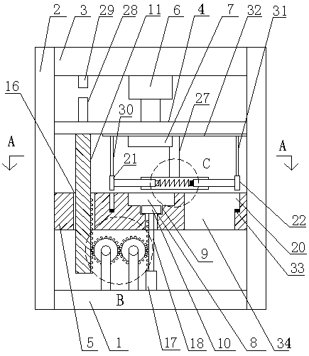
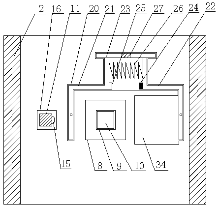
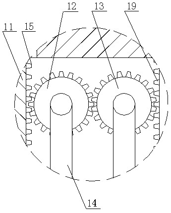
[0020] like Figure 1 to Figure 4 As shown, a stamping device for automatic demoulding includes a base 1, and vertical plates 2 are arranged on both sides of the base, and a top plate 3, an upper mold base 4 and a lower mold base 5 are sequentially arranged between the two vertical plates, and the top plate A hydraulic cylinder 6 is connected to the upper die base, and a punching head 7 is provided at the bottom of the upper die base. The demoulding mechanism includes a demoulding groove 9, a demoulding module 10, a lifting rod 11, a telescopic rod, a gear A12 and a gear B13. They are all rotated and installed on the base through the support rod 14. One side of the gear A meshes with the gear B, and the other side meshes with the tooth pattern A1...


PUM


Abstract

The invention discloses a stamping device for automatic demoulding, which comprises a base, vertical plates are arranged on both sides of the base, and a top plate, an upper mold base and a lower mold base are sequentially arranged between the two vertical plates, and the top plate and the upper mold base are A hydraulic cylinder is connected between them, and a stamping head is provided at the bottom of the upper die base, and the punching head cooperates with the punching groove on the lower die base, and a demoulding mechanism is provided between the lower die base and the base, and the demoulding mechanism includes a demoulding mechanism. Groove, stripping module, lifting rod, telescopic rod, gear A and gear B, the demoulding groove is set at the bottom of the stamping groove, and the stripping groove is equipped with a stripping module, and both gear A and gear B are installed on the base through the rotation of the pole. One side of gear A meshes with gear B, and the other side meshes with tooth pattern A on the side of the lifting rod. The upper end of the lifting rod passes through the guide hole on the lower die base and is connected to the upper die base. The tube and the movable rod arranged in the hollow tube, the side of the movable rod is provided with the teeth pattern B which meshes with the gear B, and the upper end of the movable rod is connected with the detachment module.

Description

technical field [0001] The invention belongs to the technical field of mechanical processing, and in particular relates to a stamping device for automatic mold removal. Background technique [0002] Stamping die is a special process device for processing materials (metal or non-metal) into parts (or semi-finished products) in cold stamping processing, called cold stamping die (commonly known as cold stamping die), which is widely used in mold manufacturing , is welcomed by people. However, after the stamping of the existing stamping die device is completed, the mold is subjected to a greater pressure. After the mold is formed, the mold is located inside the stamping groove, and the mold needs to be removed manually from the inside of the stamping groove, but the bonding force between the mold and the stamping groove is relatively high. Large, it is difficult for the operator to take it out, which increases the workload of the operator, and also has certain potential safety ...

Claims


Application Information

Patent Timeline
IPC IPC(8): B21D45/04
CPCB21D45/04
Inventor 彭安华杜爱民
Owner SUQIAN GENERAL MACHINERY
Why Eureka
Try Eureka