
Classification type industrial molten metal separation equipment for metallurgy

An industrial metal and liquid separation technology, applied in separation methods, filtration separation, fixed filter element filters, etc., can solve the problems of high labor intensity, low separation efficiency, and long time consumption.

Active Publication Date: 2022-04-29
江西华正智能装备有限公司
View PDF9 Cites 0 Cited by
  • Summary
  • Abstract
  • Description
  • Claims
  • Application Information

AI Technical Summary

Problems solved by technology

[0004] In order to overcome the conventional method of manual separation in the prior art, the user first pours the raw materials into the filter net for preliminary filtration, and at the same time, it takes a long time for the user to clean up the impurities on the filter net, and the user has to pour the raw material into the filter net The chemical reagent reacts with the filtered liquid to generate molten metal. Manual separation not only takes a lot of time, but also has low separation efficiency. The user has the disadvantage of high labor intensity when separating a large number of raw materials. The technical problem of the present invention is: to provide a Classified industrial metal liquid separation equipment for metallurgy with automatic separation, automatic push and interval discharge

Method used


Image

  • Classification type industrial molten metal separation equipment for metallurgy
  • Classification type industrial molten metal separation equipment for metallurgy
  • Classification type industrial molten metal separation equipment for metallurgy

Examples


Embodiment 1

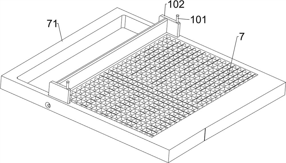
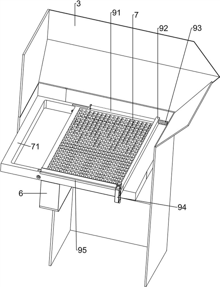
[0070] A classified type metallurgical industrial liquid metal separation equipment, such as Figure 1-7 As shown, it includes a support frame 1, a discharge frame 2, a frame 3, a solid discharge pipe 4, a liquid filling tank 5, a reaction liquid storage tank 6, a first filter screen 7, a second filter screen 8, and a liquid outlet pipeline 61 , a fixed frame 71, a pusher mechanism 9 and an opening and closing mechanism 10, a support frame 1 is arranged symmetrically on both sides of the top of the discharge frame 2, and a frame 3 is arranged on the top of the discharge frame 2, and the left side of the top of the frame 3 is connected to the discharge frame. A solid discharge pipe 4 is connected between the left side of the top of the material rack 2, a liquid filling tank 5 is provided on the upper part of the inner wall of the frame 3, a reaction liquid storage tank 6 is provided on the left side of the upper part of the inner wall of the frame 3, and a reaction liquid storag...

Embodiment 2

[0077] On the basis of Example 1, such as Figure 8-16 Shown, also comprise turning mechanism 11, turning mechanism 11 comprises arc block 111, closing frame 112, the 3rd spring 113 and projection 114, and fixed frame 71 bottom left side rotation type is provided with closing frame 112, and closing frame 112 front An arc block 111 is provided at the top, the closing frame 112 is rotatably connected with the fixed frame 71, the closing frame 112 is rotatably connected with the frame 3, the closing frame 112 is wound with a third spring 113, and the third spring 113 is connected between the closing frame 112 and the frame 3, the front and rear sides of the arc block 111 are provided with projections 114, the projections 114 on the same side cooperate with the door stop frame 102 on the same side, and the long rod 95 cooperates with the arc block 111.

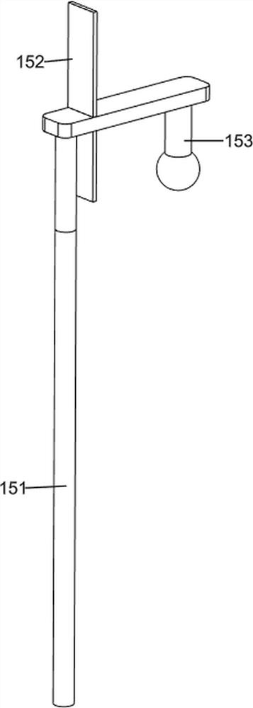
[0078] The long rod 95 moves to the left to drive the arc block 111 to rotate, thereby driving the protrusion 114 and the closin...


PUM


Abstract

The invention relates to separation equipment, in particular to classification type industrial molten metal separation equipment for metallurgy. The invention provides classified metallurgical industrial molten metal separation equipment with automatic separation, automatic material pushing and interval discharging. Classification type metallurgical industrial molten metal separation equipment comprises supporting frames and a discharging frame, and the supporting frames are symmetrically arranged on the two sides of the upper portion of the discharging frame; and the frame is arranged on the top of the discharging frame. According to the device, the material pushing mechanism is arranged, the material pushing mechanism is matched with the opening and closing mechanism, the opening and closing mechanism can prevent raw materials from falling onto the solid discharging pipe, a first filter screen can preliminarily separate the raw materials, liquid and tiny solids on the raw materials can fall into the liquid containing box, and a chemical reagent reacts with the liquid to generate needed molten metal; and tiny solids and required molten metal can fall onto the second filter screen, and the second filter screen can filter the required molten metal again, so that the work of automatically separating the molten metal is realized.

Description

technical field [0001] The invention relates to a separation device, in particular to a sorted industrial metal liquid separation device for metallurgy. Background technique [0002] With the development of social economy, molten metal technology is mainly used in the field of consumer electronics. It has the characteristics of plasticity after melting, high hardness, corrosion resistance, and high wear resistance. The existing technology generally adopts the method of manual separation. The raw materials are poured into the filter for preliminary filtration, and it takes a long time for the user to clean up the impurities on the filter, and the user also needs to pour in chemical reagents to react with the filtered liquid to form molten metal. Manual separation not only requires A lot of time, and the separation efficiency is low, and the labor intensity is high when the user separates a large number of raw materials. [0003] For this reason, we design a kind of classific...

Claims


Application Information

Patent Timeline
Patent Type & Authority Applications(China)
IPC IPC(8): B01D36/00B01D29/56B01D29/01B01D29/94
CPCB01D36/00B01D29/56B01D29/01B01D29/014B01D29/94Y02P10/20
Inventor 曾飞龙
Owner 江西华正智能装备有限公司
Learn More