Pulsating reciprocating type hydraulic pumping unit

A pumping unit, reciprocating technology, applied in the field of pulsating reciprocating hydraulic pumping unit, can solve the problems of high installed power, poor braking control, low efficiency, etc., achieve the requirements of light weight, reduce working conditions, avoid large The effect of a horse-drawn trolley

Inactive Publication Date: 2012-05-02
INNER MONGOLIA UNIV OF TECH
View PDF6 Cites 11 Cited by
  • Summary
  • Abstract
  • Description
  • Claims
  • Application Information

AI Technical Summary

Problems solved by technology

The common characteristics of mechanical rod pumping units are durability, convenient maintenance, and good reliability, but they also have obvious defects such as large installed power, high energy consumption, low efficiency, and poor braking control.

Method used


Image

  • Pulsating reciprocating type hydraulic pumping unit
  • Pulsating reciprocating type hydraulic pumping unit
  • Pulsating reciprocating type hydraulic pumping unit

Examples


Embodiment Construction

[0027] The present invention will be described in further detail below in conjunction with the accompanying drawings and specific embodiments.

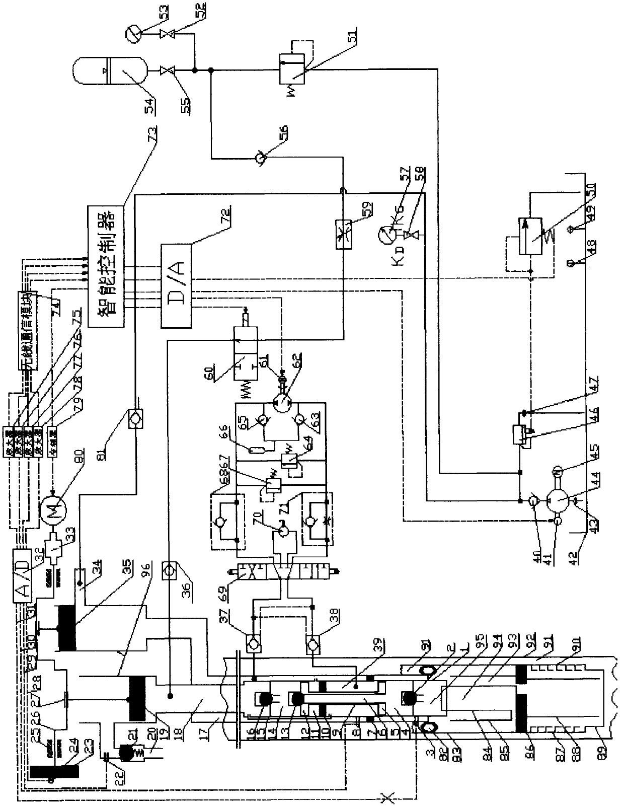
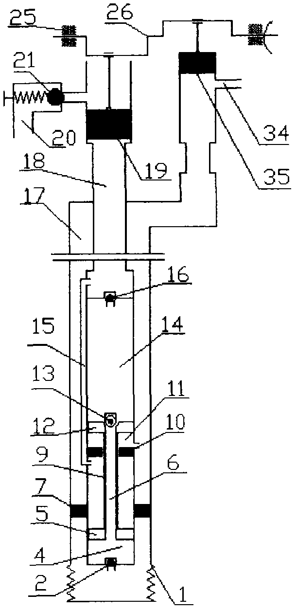
[0028] refer to figure 1 , the oil-gas mixture will go through the whole process of the oil-gas separator, that is, the crude oil (containing gas) enters the wellbore 90, and during the upstroke of the pump, the oil-gas mixture goes down from the liquid inlet pipe 87 and enters the central pipe 88, and some large bubbles are released from the mixture. It is separated from the middle and goes upward, discharged from the liquid inlet hole 92, and enters the oil jacket annulus 91 to complete the first separation, that is, gravity separation. However, most of the small air bubbles are still carried by the liquid to continue upward through the central tube 88, and enter the spiral tube 84 through the special joint 86. After the mixed liquid enters the spiral channel 93, the liquid and the gas make circular motions along the axis at the sa...


PUM


Abstract

The invention discloses a pulsating reciprocating type hydraulic pumping unit, which comprises a balanced type piston pump, a piston rod, a pulsating type piston pump, another pulsating type piston pump, an oil outlet valve, an oil filling valve and piston valve, a gas-liquid separator, a fluid replacement loop and a safe loop. The gas-liquid separator is arranged at the lower end of a pumping unit, the balanced piston pump is arranged at the middle part of the pumping unit, and the pulsating type piston pump is arranged at the upper end of the pumping unit. The pulsating reciprocating type hydraulic pumping unit disclosed by the invention has the characteristics of simple structure, convenience for operation, high efficiency, flexibility and strong applicability.

Description

technical field [0001] The invention relates to an oil pumping device of a pulsating reciprocating hydraulic cylinder, in particular to a pulsating reciprocating hydraulic oil pumping unit. Background technique [0002] At present, there are many types of pumping units widely used in oil exploitation, with various structural forms. , chain pumping unit and sliding flexible pumping unit, etc. The common characteristics of mechanical rod pumping units are durability, convenient maintenance, and good reliability, but they also have obvious defects such as large installed power, high energy consumption, low efficiency, and poor braking control. [0003] In order to solve some problems existing in the above-mentioned mechanical pumping units, people have applied hydraulic technology in the pumping unit, which can easily realize the long stroke and low stroke times of the pumping unit, and can reduce the overall weight and floor space of the pumping unit. The area is greatly red...

Claims


Application Information

Patent Timeline
Patent Type & Authority Applications(China)
IPC IPC(8): E21B43/00F04B49/00
Inventor 郭志平任志勇郭浩齐菲白福忠苗素静张国兴李宝宗
Owner INNER MONGOLIA UNIV OF TECH
Why Eureka
Try Eureka