Automatic drying system for rice

A drying system, rice technology, applied in the direction of drying, drying machine, drying solid materials, etc., can solve the problems of inconvenient and time-consuming discharging

Pending Publication Date: 2020-07-24
汉寿县德穗米业有限公司
View PDF0 Cites 1 Cited by
  • Summary
  • Abstract
  • Description
  • Claims
  • Application Information

AI Technical Summary

Problems solved by technology

[0003] However, in the prior art, it is inconvenient and time-consuming for the existing continuous drying equipment to discharge the material after drying. Therefore, it is necessary to provide a new rice automatic drying system to solve the above technical problems

Method used


Image

  • Automatic drying system for rice
  • Automatic drying system for rice
  • Automatic drying system for rice

Examples


no. 1 example

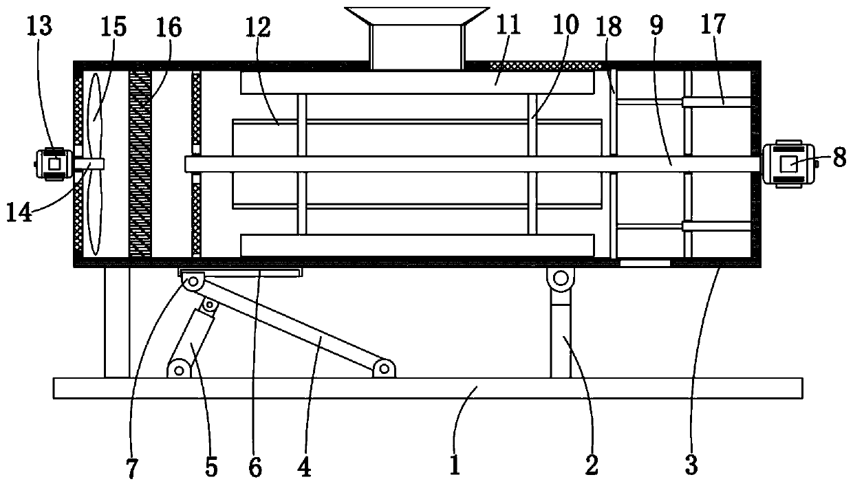
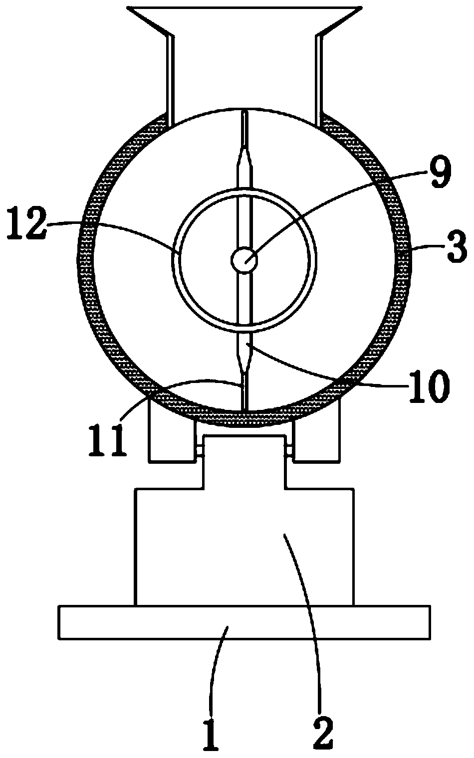
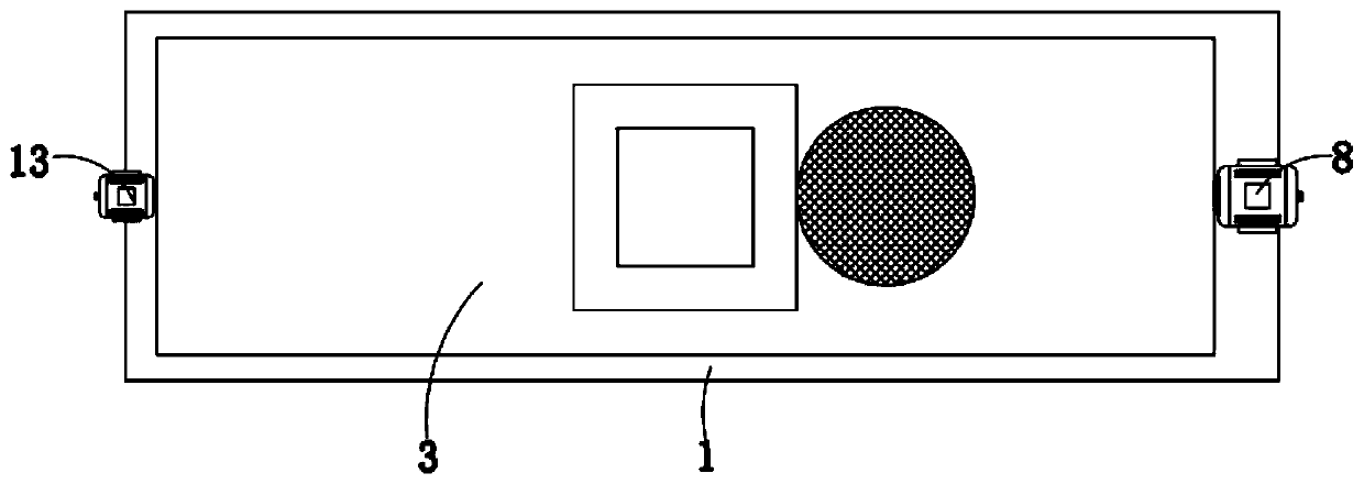
[0028] Please refer to Figure 1-Figure 3 , in the first embodiment of the present invention, the rice automatic drying system includes: a base 1; a first support plate 2, the first support plate 2 is fixedly installed on the top of the base 1; a cylinder 3, the cylinder 3 is rotatably installed on the top of the first support plate 2; the rocker 4 is rotatably installed on the top of the base 1; the hydraulic push rod 5 is rotatably installed on the top of the base 1, and the The output rod of the hydraulic push rod 5 is rotatably connected to the bottom of the seesaw 4; the slide rail 6 is fixedly installed on the bottom of the cylinder body 3; the limit slider 7 is slidably installed on the On the slide rail 6, the bottom of the limit slider 7 is rotationally connected with the top of the seesaw 4; the first motor 8, the first motor 8 is fixedly installed on the end of the cylinder 3; the rotating rod 9, the rotating The rod 9 is installed in the cylinder body 3 in rotatio...

no. 2 example

[0041] Based on the rice automatic drying system provided in the first embodiment of the present application, the second embodiment of the present application proposes another automatic rice drying system, the second embodiment is only the preferred mode of the first embodiment, the second The implementation of the embodiment has no effect on the individual implementation of the first embodiment.

[0042] The second embodiment of the present invention will be further described below in conjunction with the drawings and implementation methods.

[0043] Please refer to Figure 4-Figure 5 , in the second embodiment of the present invention, the rice automatic drying system includes: two fixed mounts 19, both fixed mounts 19 are fixedly installed on one side of the cylinder body 3, and the two fixed mounts 19 are fixedly installed with the same A conveying cylinder 20, the top of the conveying cylinder 20 is fixedly equipped with a third motor 21, and a conveying screw wheel 22 i...


PUM


Abstract

The invention provides an automatic drying system for rice. The automatic drying system for rice comprises a base, a first support plate, a barrel body, a tilting plate, a hydraulic push rod, a sliderail, a limit slide block, a first motor and a rotary rod, wherein the first support plate is fixedly installed at the top of the base; the barrel body is rotationally installed at the top of the first support plate; the tilting plate is rotationally installed at the top of the base; the hydraulic push rod is rotationally installed at the top of the base, and an output rod of the hydraulic push rod is rotationally connected with the bottom of the tilting plate; the slide rail is fixedly installed at the bottom of the barrel body; the limit slide block is slidably installed on the slide rail, and the bottom of the limit slide block is rotationally connected with the top of the tilting plate; the first motor is fixedly installed at one end of the barrel body; and the rotary rod is rotationally installed in the barrel body. The automatic drying system for rice has the advantages of being convenient to use, and capable of automatically discharging rice after completing drying.

Description

technical field [0001] The invention relates to the technical field of drying equipment, in particular to an automatic rice drying system. Background technique [0002] Rice is one of the staple foods of human beings. According to modern nutritional analysis, rice contains protein, fat, vitamin B1, A, E and various minerals. If the rice contains too much water, it is prone to mildew. In order to improve For the shelf life of rice, rice needs to be dried before being packaged. At present, rice drying equipment is divided into two types. One type is flow-type drying equipment. The advantage of flow-type drying equipment is high drying efficiency, but It is indeed because the drying time is short and the drying effect is poor. There is also a continuous drying equipment, whose advantage is that the drying time is controllable, which can ensure a better drying effect of rice. [0003] However, in the prior art, it is inconvenient and time-consuming for the existing continuous d...

Claims


Application Information

Patent Timeline
IPC IPC(8): F26B11/16F26B21/00F26B25/00F26B25/02F26B25/04F26B25/12F26B25/16
CPCF26B11/16F26B21/001F26B25/00F26B25/002F26B25/02F26B25/04F26B25/12F26B25/16
Inventor 龚俊龚明康
Owner 汉寿县德穗米业有限公司
Why Eureka
Try Eureka