
Plate grain scraper with location function

A technology for scraping machine and plate, applied in the field of plate scraping machine with positioning function, can solve the problems of inconvenient control of moving distance, laborious plate movement, lack of ancient rhythm, etc. Effect

Inactive Publication Date: 2018-02-09
佛山市高明富东机械制造有限公司
View PDF6 Cites 1 Cited by
  • Summary
  • Abstract
  • Description
  • Claims
  • Application Information

AI Technical Summary

Problems solved by technology

[0002] The original wood floor or compound wood floor used for decoration is usually flat or has only shallow natural groove lines. The pattern effect of these boards lacks ancient charm and beauty. In order to increase the beauty, it is necessary Scratching treatment on boards. In the prior art, people have designed and manufactured this board scraping machine, which can perform scratching operations on raw wood floors or composite wood floors. During the scratching operation of these boards, It is necessary to accurately locate the position of the board, but these boards are generally relatively large in size, and it is laborious to manually move the board, and the moving distance is not easy to control, and it is not convenient to reinforce the position of the board, which will affect the scraping of the board The efficiency of graining operation, so we propose a plate scratching machine with positioning function to solve the above problems

Method used


Image

  • Plate grain scraper with location function
  • Plate grain scraper with location function

Examples


Embodiment Construction

[0018] The following will clearly and completely describe the technical solutions in the embodiments of the present invention with reference to the accompanying drawings in the embodiments of the present invention. Obviously, the described embodiments are only some, not all, embodiments of the present invention.

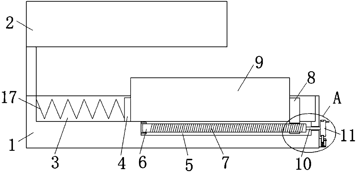
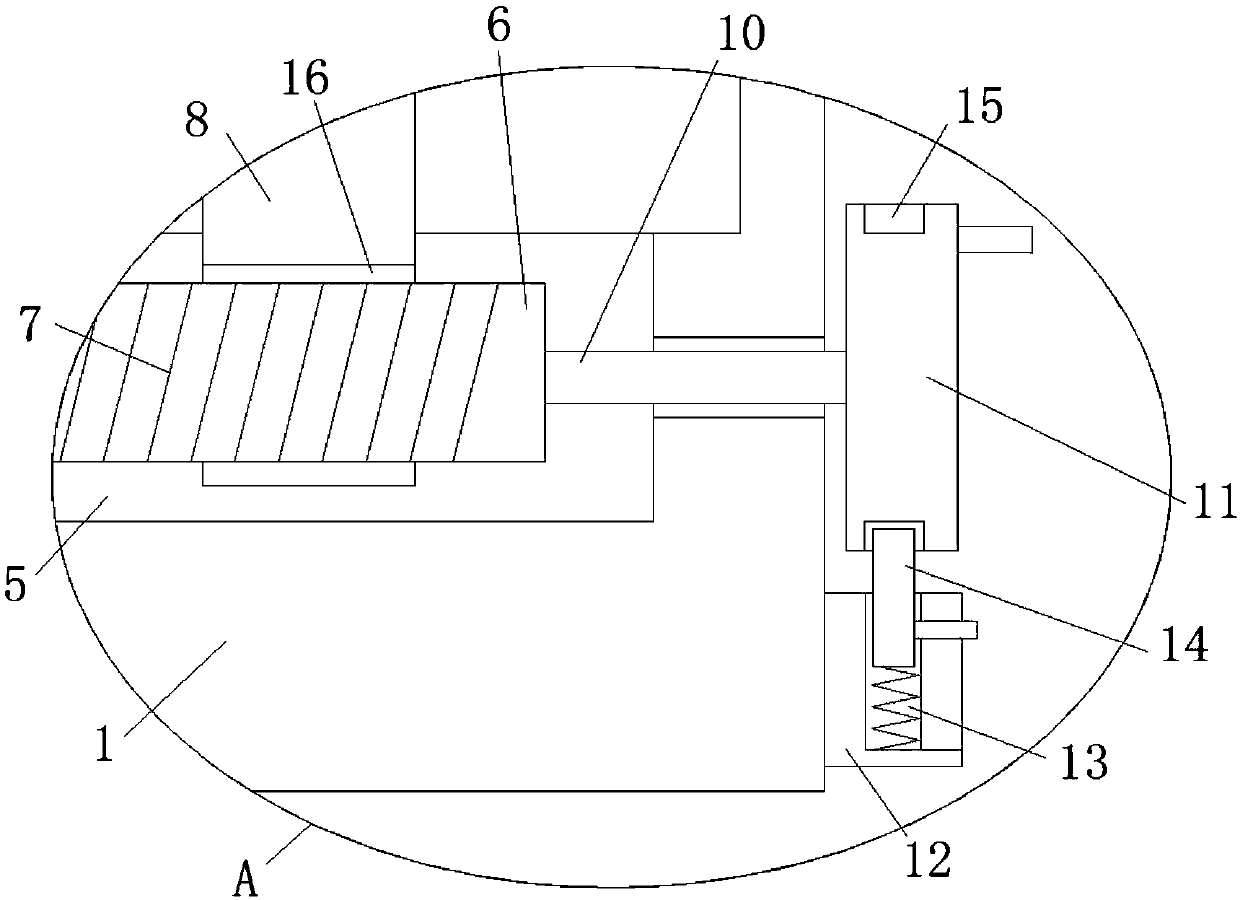
[0019] refer to Figure 1-2 , a plate scraping machine with positioning function, comprising a positioning table 1, the top of the positioning table 1 is provided with a moving groove 3, one side of the moving groove 3 is provided with a bracket fixedly installed on the top of the positioning table 1, the top of the bracket is fixed A scratching machine body 2 is installed, and a reinforcing plate 4 is slidably installed in the moving groove 3. One side of the reinforcing plate 4 is provided with an adjusting groove 5 on the inner wall of the bottom of the moving groove 3, and one side of the adjusting groove 5 is rotated on the inner wall. There is a rotating shaft ...


PUM


Abstract

The invention discloses a plate grain scraper with a location function. The plate grain scraper comprises a location table, wherein a moving groove is formed in the top of the location table; a support fixedly installed at the top of the location table is arranged at one side of the moving groove; a grain scraper body is fixedly installed at the top of the support; a reinforcing plate is slidablyinstalled in the moving groove; an adjustment groove formed in the inner wall of the bottom of the moving groove is formed in one side of the reinforcing plate; a rotary shaft is rotationally installed on the inner wall of one side of the adjustment groove; a skew rack is arranged at the outer side of the rotary shaft; a push plate is installed at the outer side of the rotary shaft through a thread; and the push plate is slidably installed in the adjustment groove, and the top of the push plate extends into the moving groove. The plate grain scraper disclosed by the invention is simple in structure and convenient to operate, and facilitates to move a plate body, so that accurate location can be carried out on the position of the plate body, the plate body can be moved to a proper position,and machining operation can be conveniently carried out on the plate body.

Description

technical field [0001] The invention relates to the technical field of plate scratching machines, in particular to a plate scratching machine with a positioning function. Background technique [0002] The original wood floor or compound wood floor used for decoration is usually flat or has only shallow natural groove lines. The pattern effect of these boards lacks ancient charm and beauty. In order to increase the beauty, it is necessary Scratching treatment on boards. In the prior art, people have designed and manufactured this board scraping machine, which can perform scratching operations on raw wood floors or composite wood floors. During the scratching operation of these boards, It is necessary to accurately locate the position of the board, but these boards are generally relatively large in size, and it is laborious to manually move the board, and the moving distance is not easy to control, and it is not convenient to reinforce the position of the board, which will aff...

Claims


Application Information

Patent Timeline
Patent Type & Authority Applications(China)
IPC IPC(8): B27M1/00B25B11/00
CPCB25B11/00B27M1/003
Inventor 李永富
Owner 佛山市高明富东机械制造有限公司
Learn More