Battery charging control circuit

A control circuit and battery charging technology, applied in battery circuit devices, different battery charging, circuit devices, etc., can solve the problems of battery overcharging, lower production efficiency, battery defect rate, etc., achieve good contact, avoid overcharging, The effect of ensuring the accuracy of collection

Pending Publication Date: 2018-02-09
OPTIMUM BATTERY CO LTD
View PDF0 Cites 1 Cited by
  • Summary
  • Abstract
  • Description
  • Claims
  • Application Information

AI Technical Summary

Problems solved by technology

[0002] The existing battery pre-charging cabinet is relatively simple, and the battery pre-charging cabinet adopts the structure of the needle bed, and there is a phenomenon of poor contact between the battery and the probe every time the needle bed is pressed down. If it is used for a long time, due to the occurrence of The jitter of the battery pre-charging node is likely to cause the loosening of the connecting line of the battery pre-charging node. Therefore, the battery pre-charging cabinet will increase the defect rate of the battery and reduce the production efficiency.
In addition, the battery charging line is long. When the charging current exceeds 2A, there will be tens of millivolts of line loss and voltage drop difference on the charging line.
If a batch of batteries is charged for a long time, the internal resistance of individual batteries is too large, and the monitoring of the charging process is lacking or the monitoring accuracy is not enough, which will lead to overcharging of the battery

Method used


Image

  • Battery charging control circuit
  • Battery charging control circuit
  • Battery charging control circuit

Examples


Embodiment Construction

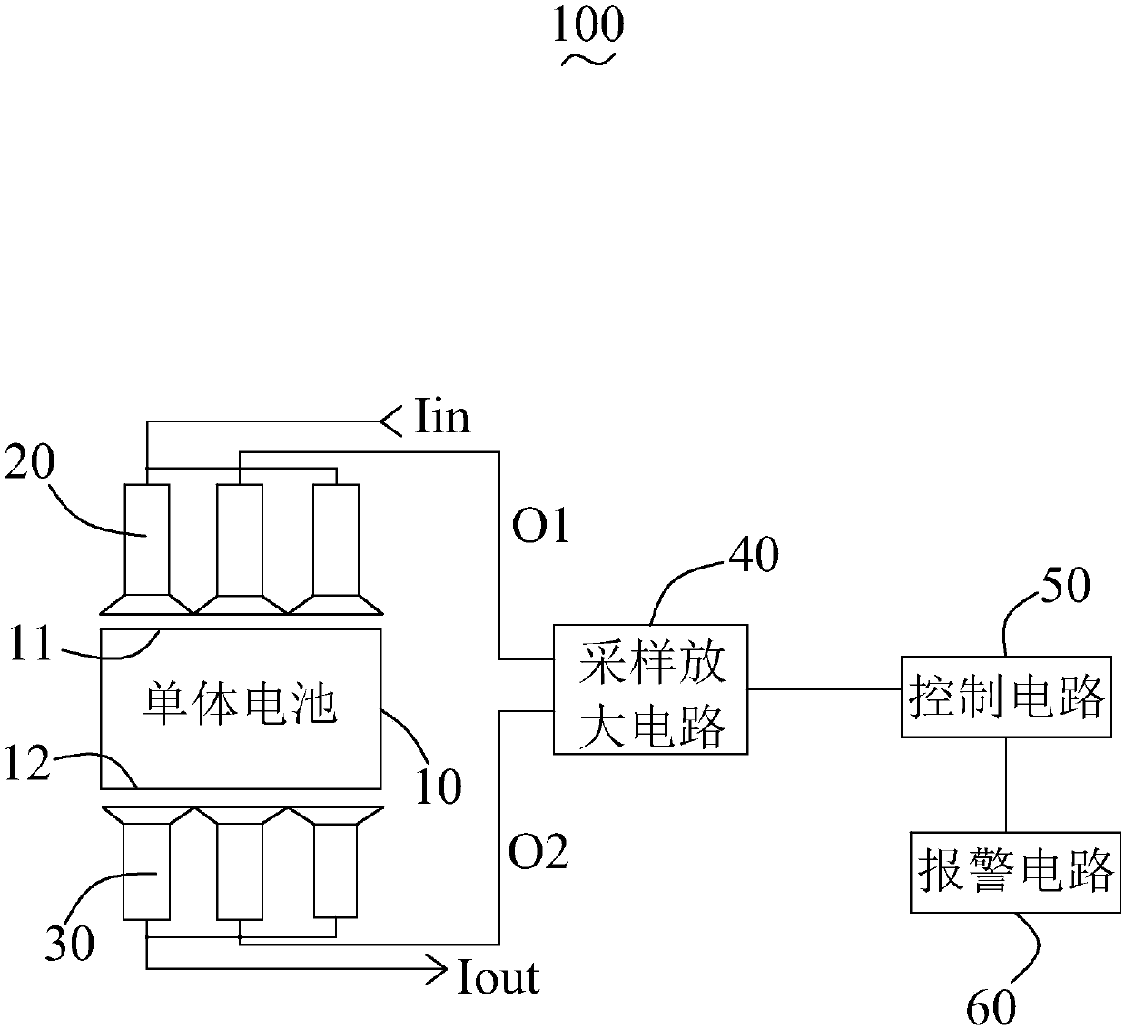
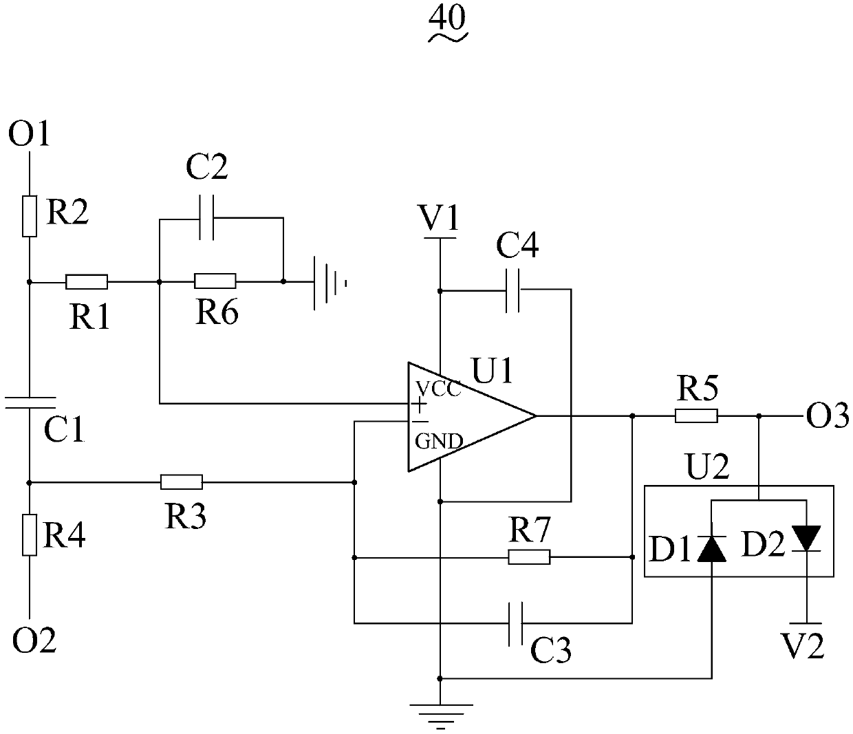
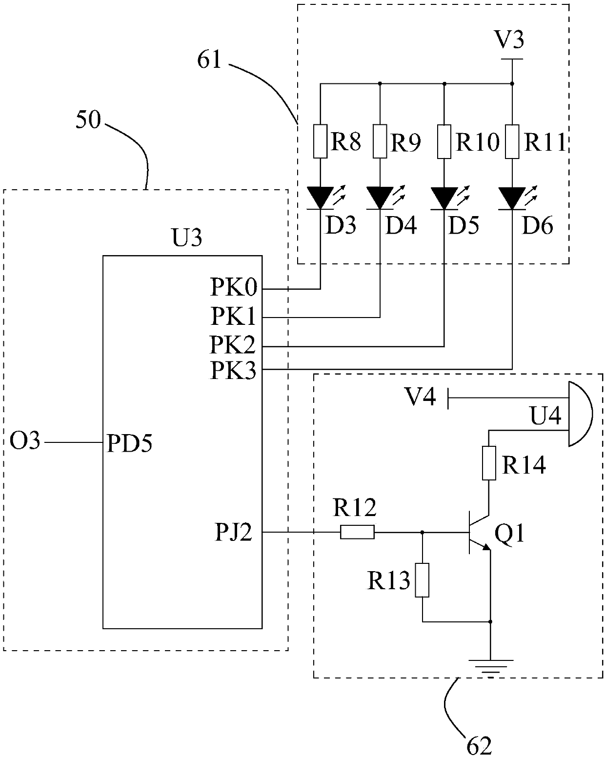
[0019] In order to make the objectives, technical solutions and beneficial technical effects of the present invention clearer, the technical solutions in the embodiments of the present invention will be clearly and completely described below in conjunction with the accompanying drawings in the embodiments of the present invention. Obviously, the described implementation The form is only a part of embodiments of the present invention, not all of them. Based on the implementation manners in the present invention, all other implementation manners obtained by persons of ordinary skill in the art without making creative efforts belong to the scope of protection of the present invention.

[0020] When an element is referred to as being "connected to" another element, it can be directly connected to the other element or intervening elements may also be present. Unless otherwise defined, all technical and scientific terms used herein have the same meaning as commonly understood by one...


PUM


Abstract

The invention discloses a battery charging control circuit comprising a single battery, multiple first probes, multiple second probes, a sampling and amplifying circuit, a control circuit and an alarmcircuit. The single battery comprises a positive electrode and a negative electrode. Multiple first probes are electrically interconnected and one end is electrically connected with the positive electrode of the single battery and the other end is connected with the sampling and amplifying circuit. Multiple second probes are electrically interconnected and one end is electrically connected with the negative electrode of the single battery and the other end is connected with the sampling and amplifying circuit. The other end of multiple first probes is also connected with a charging current input end, and the other end of multiple second probes is also connected with a charging current output end. The control circuit is connected with the sampling and amplifying circuit and the alarm circuit. The sampling and amplifying circuit is used for acquiring the charging voltage of the positive electrode of the single battery and the charging voltage of the negative electrode and amplifying thevoltage difference of the charging voltage of the positive electrode and the charging voltage of the negative electrode and then transmitting the voltage difference to the control circuit. When the voltage difference is greater than the preset voltage, the control circuit controls the alarm circuit to alarm.

Description

【Technical field】 [0001] The invention relates to the technical field of batteries, in particular to a battery charging control circuit. 【Background technique】 [0002] The existing battery pre-charging cabinet is relatively simple, and the battery pre-charging cabinet adopts the structure of the needle bed, and there is a phenomenon of poor contact between the battery and the probe every time the needle bed is pressed down. If it is used for a long time, due to the occurrence of The jitter of the battery pre-charging node is likely to cause loosening of the connecting line of the battery pre-charging node. Therefore, the battery pre-charging cabinet will increase the defect rate of the battery and reduce the production efficiency. In addition, the battery charging line is long. When the charging current exceeds 2A, there will be a line loss voltage drop of tens of millivolts on the charging line. If a batch of batteries is charged for a long time, the internal resistance o...

Claims


Application Information

Patent Timeline
Patent Type & Authority Applications(China)
IPC IPC(8): H02J7/00
CPCH02J7/00H02J7/0045H02J7/0047
Inventor 邓子军
Owner OPTIMUM BATTERY CO LTD
Why Eureka
Try Eureka