

im server deployment method and system
A server and home server technology, applied in transmission systems, digital transmission systems, data exchange networks, etc., can solve problems such as not being able to meet complex network environments well, and achieve the effect of ensuring load balancing
Active Publication Date: 2021-01-19
PRANUS BEIJING TECH CO LTD
View PDF9 Cites 0 Cited by
- Summary
- Abstract
- Description
- Claims
- Application Information
AI Technical Summary
Problems solved by technology
However, existing deployment methods cannot well meet the needs of complex network environments
Method used
View moreImage
Smart ImageViewing Examples

Examples
Embodiment approach
[0042] According to an embodiment of the system of the present invention, the system further includes a routing module, configured to route communications between users through their respective home servers.
Login to View More PUM
 Abstract
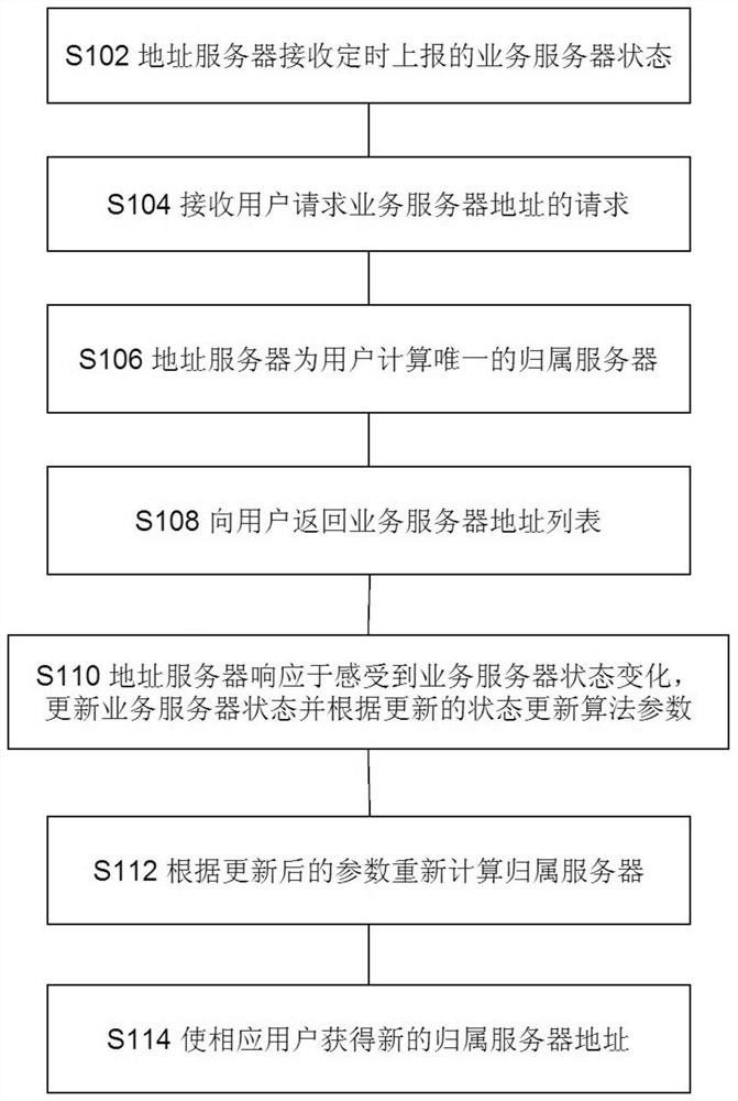
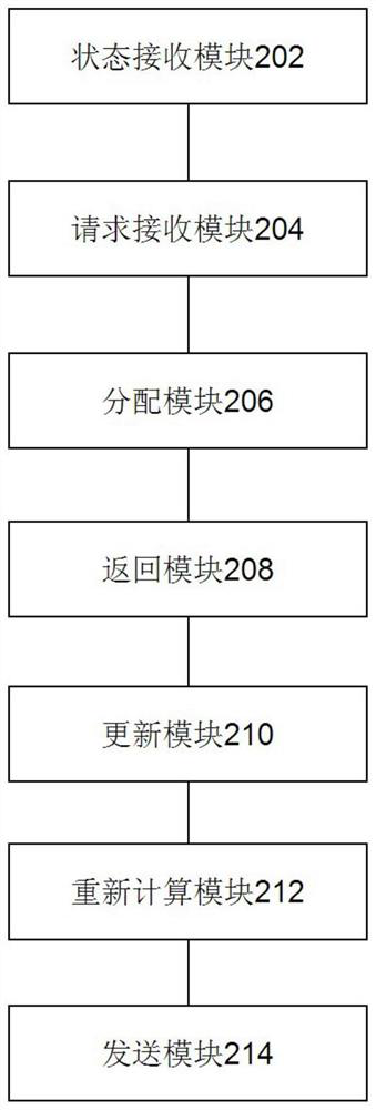
The invention discloses an IM server deployment method and a system. An IM server comprises an address server and service servers which are deployed in a distributed mode. The address server is used for distributing addresses of the service servers providing services for a user. The e service servers provide a service function. The address server is communicated with the service servers. The service servers are connected to each other through an IP. The method comprises the following steps of in the address server, receiving service server states reported by the service servers at regular time; receiving a request of a user requesting for the addresses of the service servers; distributing an attribution server for the user who submits the request, wherein the attribution server is a preferred service server capable of providing a service for the user; and returning a service server address list in which the addresses are ranked according to priorities to the user, wherein the attribution server possesses the highest priority. By using the method and the system of the invention, each node can provide the service independently, dynamic expansion or deletion of the nodes does not influence the services, and centerless distributed deployment of an IM server is realized.
Description
technical field [0001] This application relates to the field of digital information transmission, in particular to an IM server deployment method and system. Background technique [0002] When the centralized deployment of IM (Instant Messaging / Instant Messaging) server groups cannot meet specific application scenarios, distributed IM server deployment solutions are increasingly being mentioned and applied. Traditional IM servers are generally deployed centrally in the computer room, and multiple servers form a cluster to provide external services in a unified manner. With the development of cloud service technology, many services can be deployed on third-party cloud servers, which saves enterprises a series of troubles such as equipment management and computer room management. IM service companies can also deploy services to third-party cloud servers, allowing companies to focus more on software implementation, while saving hardware management costs for companies. However...
Claims
Login to View More Application Information
Patent Timeline
 Patent Type & AuthorityPatents(China)
IPC IPC(8): H04L29/08H04L12/58
CPCH04L51/04H04L67/1008H04L67/1012H04L67/1034
Inventor吴蓓
OwnerPRANUS BEIJING TECH CO LTD