Railway fastener abnormality detection system based on monocular vision and laser speckles
A laser speckle, monocular vision technology, applied in railway car body parts, railway vehicle shape measuring instruments, optical test flaws/defects, etc. The fastener gasket is missing and the fastener elastic strip is partially damaged, which can increase the artificial texture, eliminate foreign objects on the railway, and reduce the computational complexity.
- Summary
- Abstract
- Description
- Claims
- Application Information
AI Technical Summary
Problems solved by technology
Method used
Image
Examples
Embodiment 1
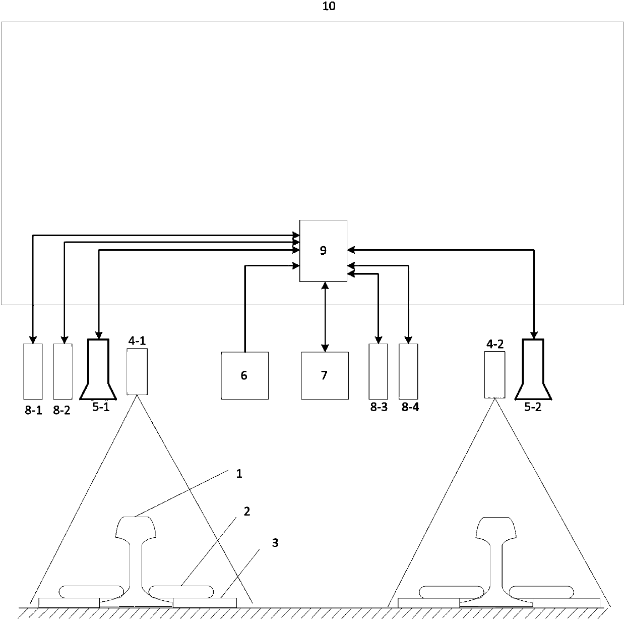
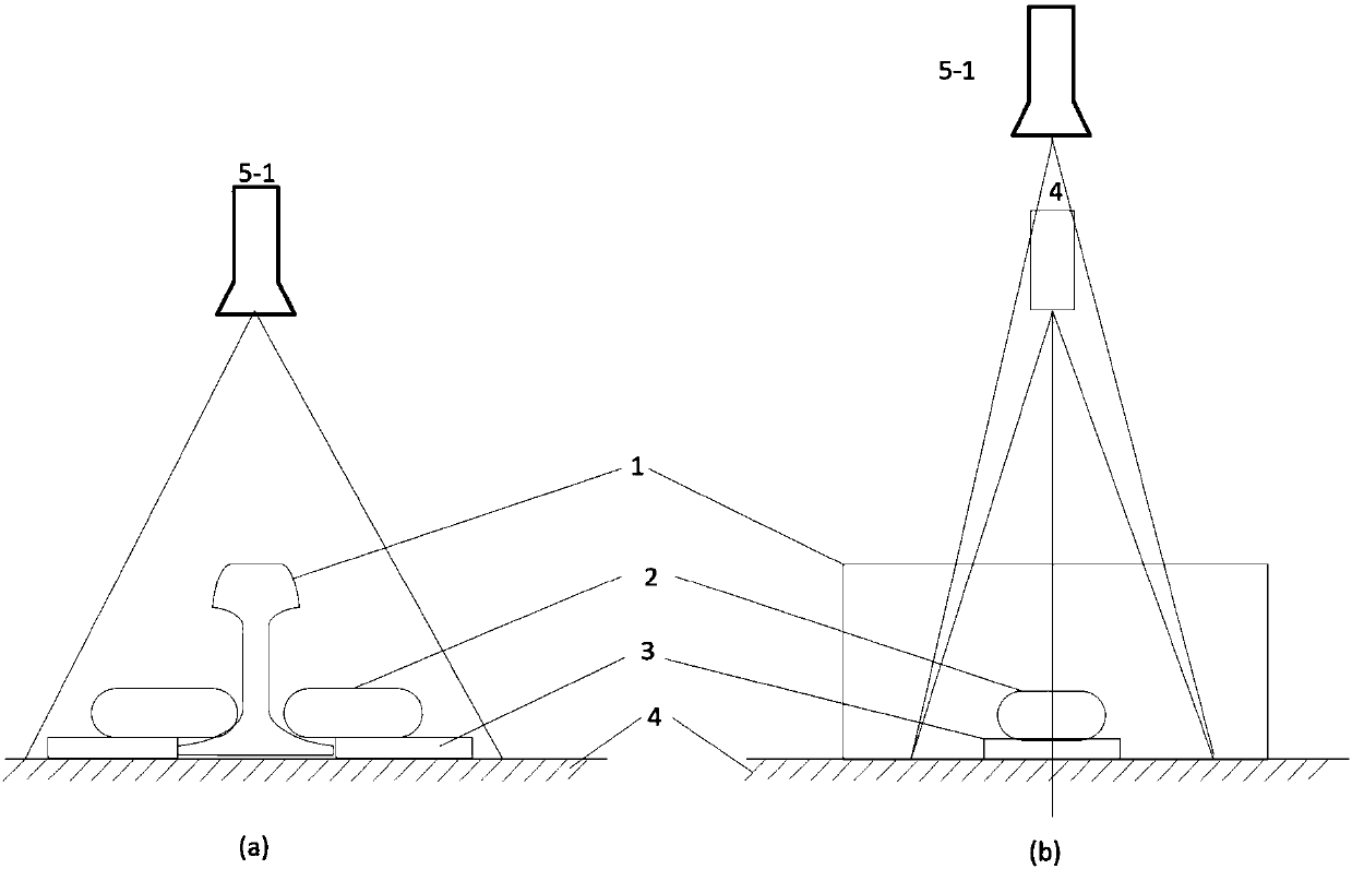
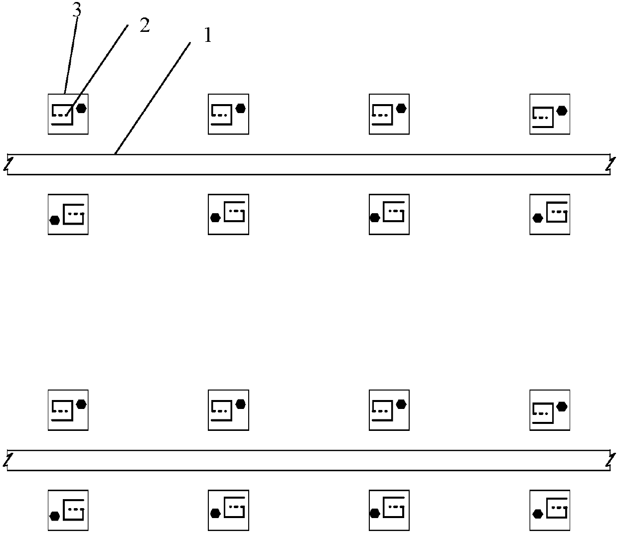
[0050] Such as figure 1 As shown, a rail fastener anomaly detection system based on monocular vision and laser speckle is characterized in that: two laser speckle projectors Sa4-1 and Sb4-2, two cameras Ca5-1 and Cb5- 2. Four laser displacement sensors La8-1, Lb8-2, Lc8-3, Ld8-4, 1 wheel encoder 6, 1 RFID detector 7 and 1 industrial computer 9, among which the laser speckle projection The detector Sa4-1 and the camera Ca5-1 are located on the left side of the bottom of the train, forming the first measurement unit 21 to detect the fasteners 2 on both sides of the left rail 1; the laser speckle projector Sb4-2 and the camera Cb5-2 are located on the train The right side of the bottom constitutes the second measurement unit 22, which detects the fasteners 2 on both sides of the right rail 1; the laser speckle projector 4 and the camera 5 are located directly above the rail 1; the laser speckle projector 4 projects a speckle pattern 19 to the surface of the fastener 2, the camer...
Embodiment 2
[0074] The difference from Example 1 is that, as Figure 9 As shown, the detection device also includes: the first and second measuring units 21 and 22 use hard rubber pads 26 or plastic gaskets as passive damping structures 25 and are fixed to the support beam 23, between the support beam 23 and the train bogie 24 K springs are connected in parallel, and the value of k ranges from 1 to 10.
Embodiment 3
[0076] The difference from Embodiment 1 is that the four laser displacement sensors 8 adopt another installation method: as Figure 6 As shown, the laser displacement sensor La8-1 is located in the first or second measuring unit 21 and 22 public field of view, the road plane 11 is perpendicular to the central axis 12 plane of the rail, and the laser displacement sensor Lb8-2 is arranged longitudinally along the rail 1 At the position of laser displacement sensor La8-1d1, the horizontal distance between laser displacement sensors La8-1 and Lb8-2 and the center line of rail 1 is equal to d2; laser displacement sensors Lc8-3 and Ld8-4 are parallel to La8-1 and Lb8-2 The connecting line is placed above the central axis 18 of the railway to measure the height of the upper surface of the sleeper 17. The distance between Lc8-3 and Ld8-4 is 1 / 2 of the width of the upper surface of the sleeper 17; La8-1 and Lc8-2 are located on the front side of the train , Lb8-3 and Ld8-4 are located ...
PUM
 Abstract
Description
Claims
Application Information
 - R&D
- Intellectual Property
- Life Sciences
- Materials
- Tech Scout
- Unparalleled Data Quality
- Higher Quality Content
- 60% Fewer Hallucinations
Browse by: Latest US Patents, China's latest patents, Technical Efficacy Thesaurus, Application Domain, Technology Topic, Popular Technical Reports.
© 2025 PatSnap. All rights reserved.Legal|Privacy policy|Modern Slavery Act Transparency Statement|Sitemap|About US| Contact US: help@patsnap.com


