Railway track fastener anomaly detection system based on binocular vision and laser speckle

A laser speckle and binocular vision technology, applied in railway car body parts, railway vehicle shape measuring instruments, optical test flaws/defects, etc. The fastener gasket is missing and the fastener elastic strip is partially damaged, which can increase the artificial texture, reduce the computational complexity and improve the efficiency.

Pending Publication Date: 2018-02-16
成都精工华耀科技有限公司
View PDF1 Cites 10 Cited by
  • Summary
  • Abstract
  • Description
  • Claims
  • Application Information

AI Technical Summary

Problems solved by technology

However, the multi-parallel light strip shape modulation method adopted by this type of method is difficult to detect the shape change of the unirradiated area of ​​the light strip. Therefore

Method used


Image

  • Railway track fastener anomaly detection system based on binocular vision and laser speckle
  • Railway track fastener anomaly detection system based on binocular vision and laser speckle
  • Railway track fastener anomaly detection system based on binocular vision and laser speckle

Examples


Example Embodiment

[0048] Example 1:

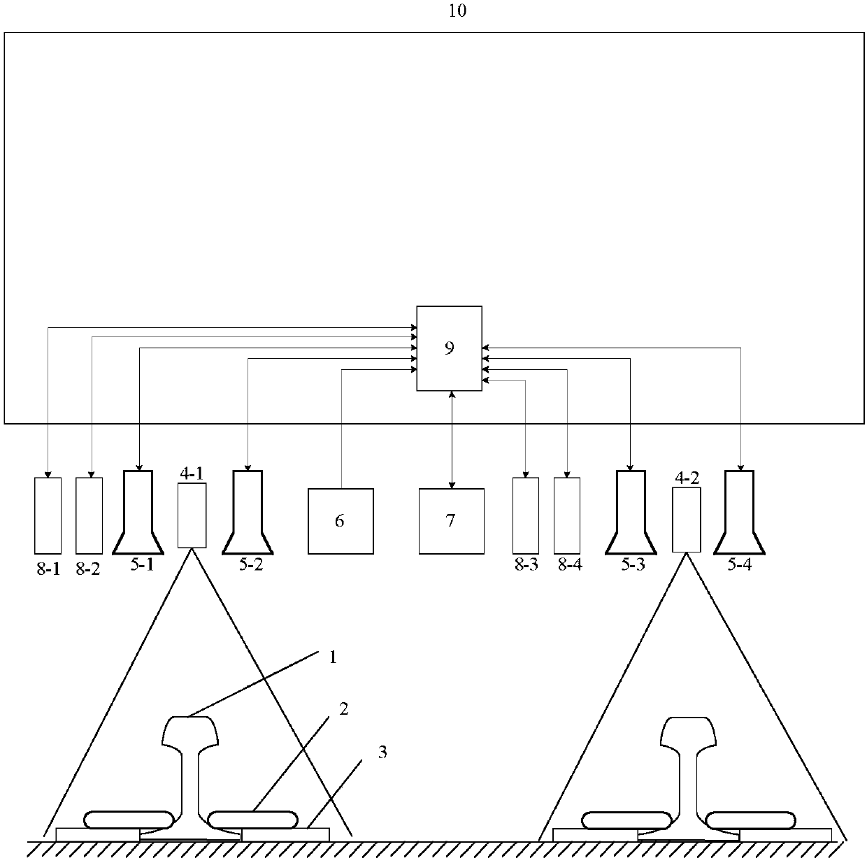
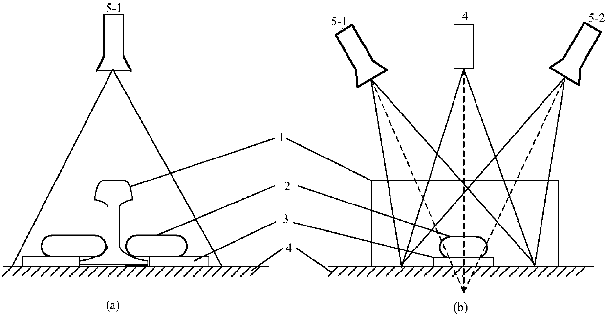
[0049] Such as figure 1 As shown, a rail fastener anomaly detection system based on binocular vision and laser speckle is composed of two laser speckle projectors Sa4-1 and Sb4-2, four cameras Ca5-1, Cb5-2, Cc5- 3. Cd5-4, four laser displacement sensors La8-1, Lb8-2, Lc8-3, Ld8-4, a wheel encoder 6, an RFID detector 7 and an industrial computer 9, including laser speckle projection Sa4-1, cameras Ca5-1 and Cb5-2 are located on the left side of the bottom of the train, constituting the first measuring unit 21 (such as Picture 9 As shown), the fasteners 2 on both sides of the left rail 1 are detected; the laser speckle projector Sb4-2, the cameras Cc5-3 and Cd5-4 are located on the right side of the bottom of the train, forming the second measurement unit 22, Fasteners 2 on both sides of rail 1 are tested; figure 2 As shown, the laser speckle projector 4 is located directly above the rail 1, and projects laser speckle 19 to the rail 1 and the fasteners 2 on b...

Example Embodiment

[0070] Example 2:

[0071] The difference from Example 1 is that Picture 9 As shown, the detection device also includes: the first and second measurement units 21 and 22 use hard rubber pads 26 or plastic pads as the passive vibration damping structure 25 to be fixed to the support beam 23, between the support beam 23 and the train bogie 24 K springs are connected in parallel, and the value of k ranges from 1 to 10.

Example Embodiment

[0072] Example 3:

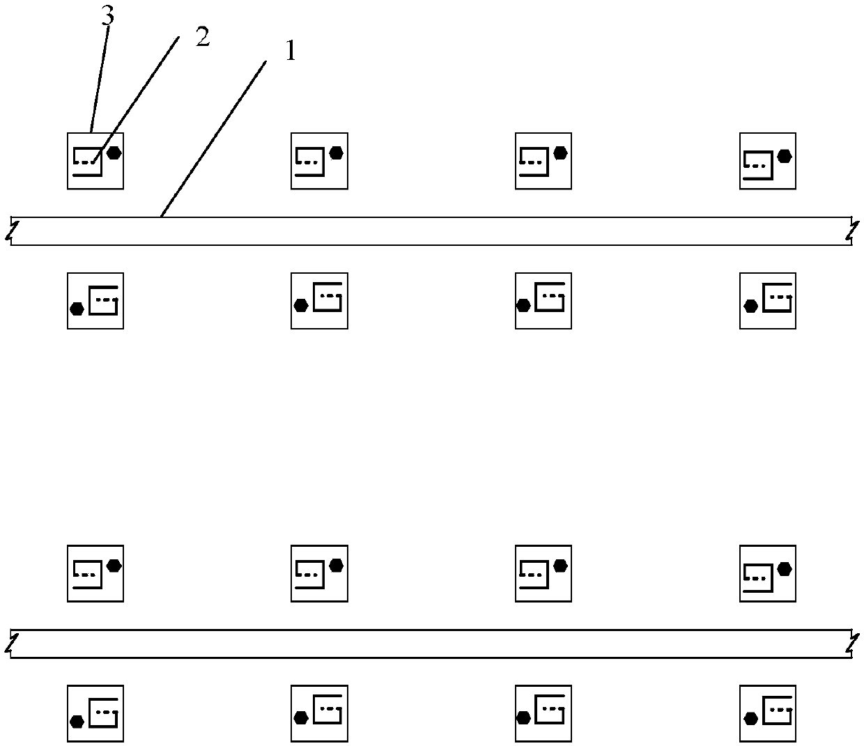
[0073] The difference from Embodiment 1 is that the four laser displacement sensors 8 adopt another installation method: Image 6 As shown, the laser displacement sensor La8-1 is located in the common field of view of the first or second measuring units 21 and 22 in the plane of the road surface 11 perpendicular to the central axis 12 of the rail, and the laser displacement sensor Lb8-2 is arranged longitudinally along the rail 1. At the position of laser displacement sensor La8-1d1, the horizontal distance between laser displacement sensors La8-1 and Lb8-2 and the center line of rail 1 is equal to d2; laser displacement sensors Lc8-3 and Ld8-4 are parallel to La8-1 and Lb8-2 The connecting line is placed above the central axis 18 of the railway to measure the height of the upper surface of the sleeper 17. The distance between Lc8-3 and Ld8-4 is 1 / 2 of the width of the upper surface of the sleeper 17; La8-1 and Lc8-2 are located on the front side of the car , ...


PUM

PropertyMeasurementUnit
Wavelengthaaaaaaaaaa

Abstract

The invention discloses a rail fastener anomaly detection system based on binocular vision and laser speckle, which is composed of a laser speckle projector, a camera, a laser displacement sensor, a wheel encoder, an RFID detector and an industrial computer. The speckle projector and the camera constitute a binocular stereo vision speckle imaging system, which is used for three-dimensional measurement of the fastener; the laser displacement sensor is used to measure the height of the fastener installation support, which is used to control the camera imaging, wheel encoder and The RFID detector is used for mileage counting, the industrial computer completes the image acquisition and processing, and the method based on binocular vision stereo matching is used to detect whether the fastener is abnormal. The device uses a laser speckle light source to artificially increase the mottled texture on the surface of the fastener, which can improve the matching accuracy of image blocks and accurately reconstruct the three-dimensional shape of the fastener, thereby effectively detecting various abnormalities of different types of fasteners.

Description

technical field [0001] The invention relates to equipment in the field of railway infrastructure detection, in particular to a rail fastener anomaly detection system based on binocular vision and laser speckle. Background technique [0002] Fasteners are components that connect rails and sleepers to form rail rows, and play an important role in ensuring track stability and reliability. In terms of railway infrastructure testing, my country has long been dominated by manual and static testing, with high maintenance costs, high strength, and poor safety. In recent years, my country's high-speed railways have developed rapidly, and higher requirements have been put forward for the automation and real-time performance of railway testing. The existing fastener detection technology at home and abroad is: continuous scanning device based on linear array laser, such as German Sick company; computer vision detection device based on area array image sensor, such as VIS system of Ameri...

Claims


Application Information

Patent Timeline
IPC IPC(8): G01N21/88B61K9/08
CPCG01N21/8851B61K9/08
Inventor 不公告发明人
Owner 成都精工华耀科技有限公司
Why Eureka
Try Eureka