Clamp and machine tool

A fixture and machine tool technology, applied in the field of fixture manufacturing, can solve the problems of waste, inability to process machine tools, increased equipment and site investment, etc., and achieve the effect of reducing installation, saving time and labor costs

Active Publication Date: 2018-02-16
西峡县众德汽车部件有限公司
View PDF6 Cites 0 Cited by
  • Summary
  • Abstract
  • Description
  • Claims
  • Application Information

AI Technical Summary

Problems solved by technology

[0004] The object of the present invention is to provide a fixture and a machine tool to alleviate the technology in the prior art that after the workpiece to be processed is fix

Method used


Image

  • Clamp and machine tool
  • Clamp and machine tool
  • Clamp and machine tool

Examples


Embodiment 1

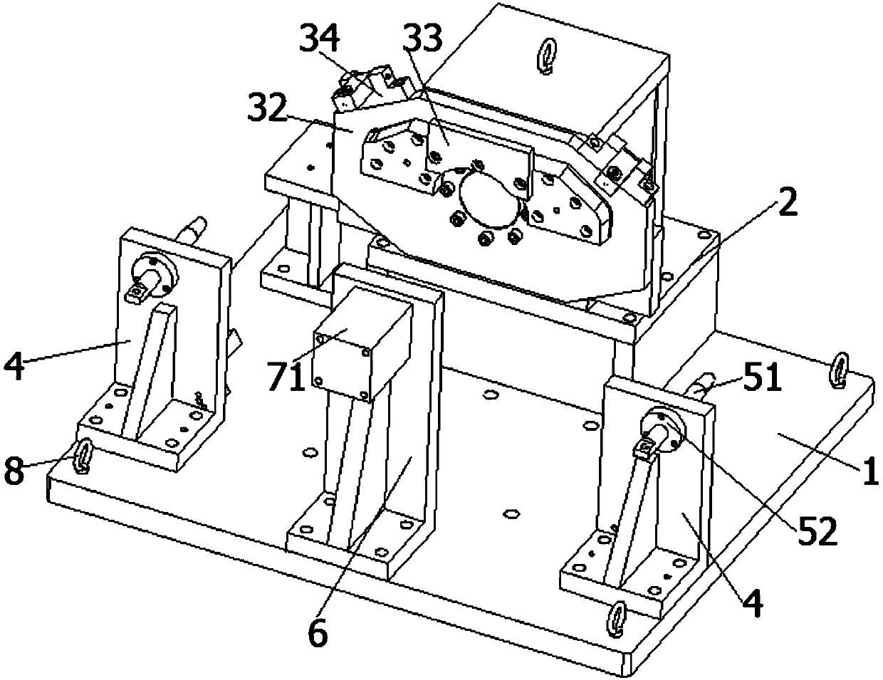
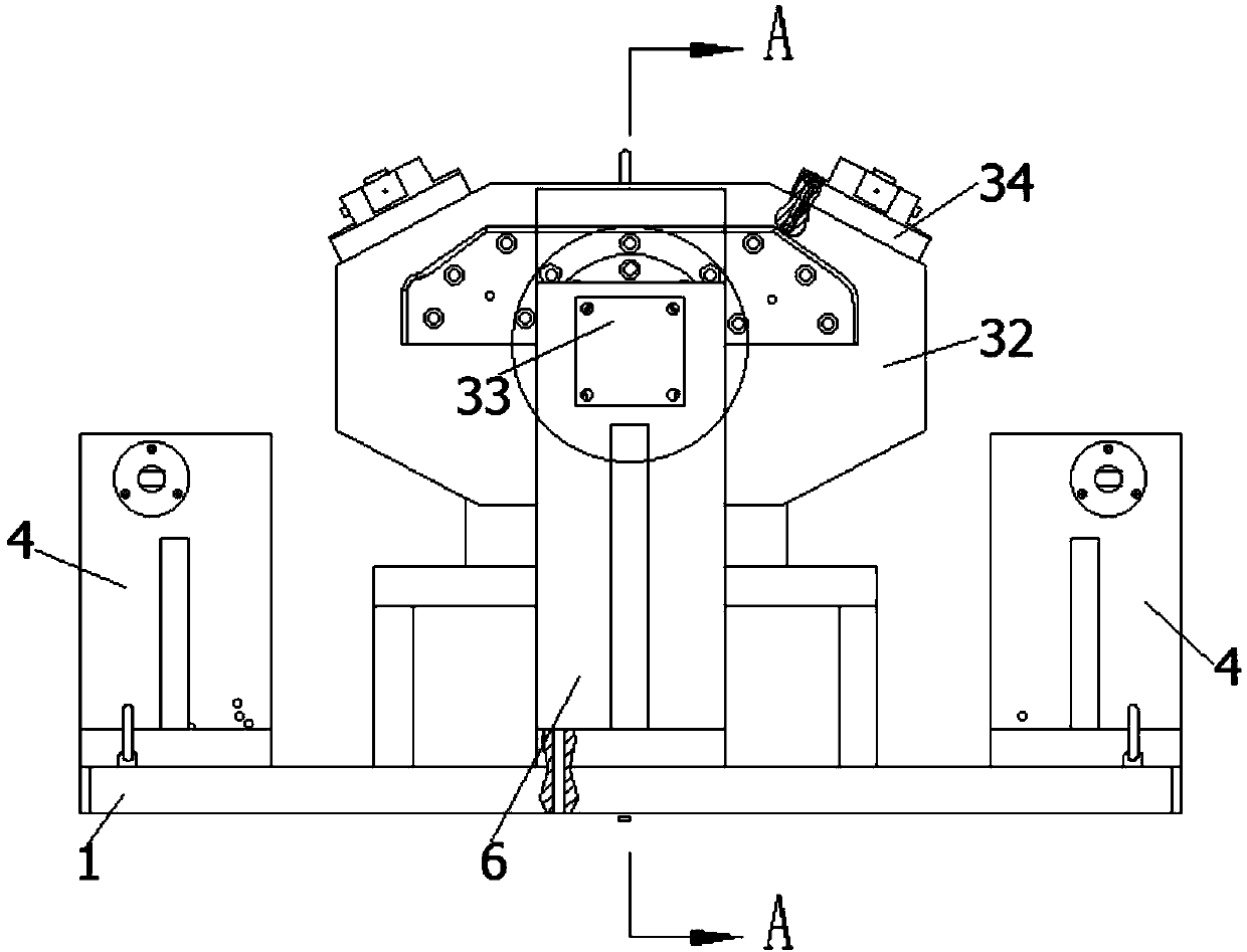
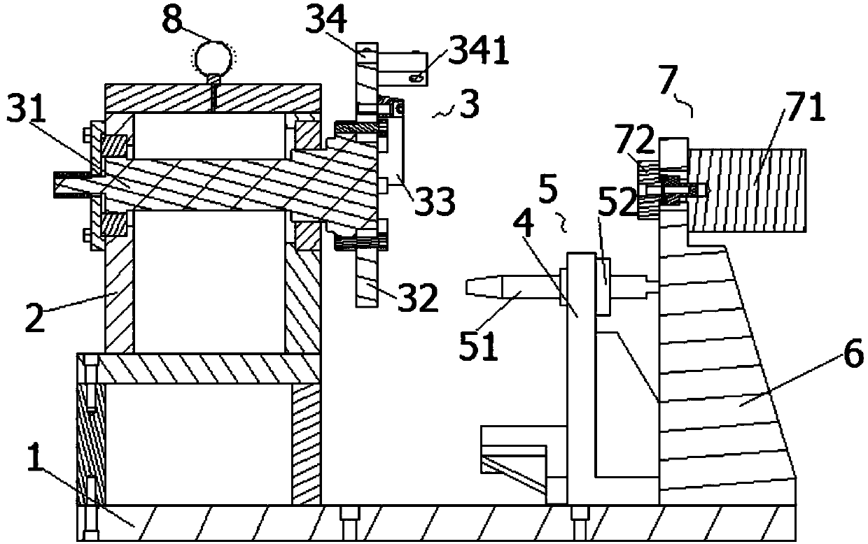
[0035] Such as figure 1 - Figure 5 As shown, the embodiment of the present invention provides a fixture, including a base 1, a fixing device and at least two positioning devices; the fixing device includes a first bracket 2 fixed on the base 1, and the first bracket 2 is pivotally connected to The fixed portion 3 of the workpiece; the positioning device includes a second support 4 fixed on the base 1, the second support 4 is provided with a positioning portion 5 that can limit the rotation of the workpiece to be processed, when the workpiece to be processed and the fixed portion 3 and the positioning When the part 5 is fixedly connected, the corresponding processing surface 91 of the workpiece to be processed faces the processing part of the machine tool.

[0036] The clamp provided by the embodiment of the present invention includes a base 1, a fixing device and at least two positioning devices, wherein the first bracket 2 in the fixing device is fixed on the base 1, and th...

Embodiment 2

[0060] An embodiment of the present invention provides a machine tool, including the above-mentioned clamp, which is detachably fixed on the machine tool.

[0061] After the fixture is fixed on the machine tool by bolts, the workpiece to be processed is fixedly connected to the fixed part 3. At this time, its rotation is restricted by a positioning device to complete the fixing of the workpiece to be processed on the base 1. At this time, one of the processing surfaces 91 Facing the processing part of the machine tool, the processing part can complete the processing of the processing surface 91. After the processing is completed, the positioning device cancels the restriction on the rotation of the workpiece to be processed, and then re-completes the positioning of the workpiece to be processed on the base 1 by another positioning device. Fixed, at this moment, another processing surface 91 is towards the processing part of machine tool, and processing part can complete the pro...


PUM


Abstract

The invention provides a clamp and a machine tool, and relates to the technical field of clamp manufacturing. The clamp comprises a base, a fixing device and at least two positioning devices; the fixing device comprises a first support fixedly arranged on the base, and a fixing part used for fixing a to-be-machined part is pivoted to the first support; the positioning devices each comprise a second support fixedly arranged on the base, and positioning parts capable of limiting rotation of the to-be-machined part are arranged on the second supports; and when the to-be-machined part is fixedly connected with the fixing part and the positioning parts, the corresponding machining surfaces of the to-be-machined part face a machining part of the machine tool. According to the clamp and the machine tool, the technical problems that equipment investment and site investment are increased and time and labor are wasted due to the fact that the other machining surfaces cannot be machined by the machine tool after the to-be-machined part is fixed by the clamp in the prior art are solved.

Description

technical field [0001] The invention relates to the technical field of jig manufacturing, in particular to a jig and a machine tool. Background technique [0002] In the processing and forming process of large parts, it is necessary to use various machine tools such as lathes, milling machines, etc. to perform multiple processes such as drilling, cutting and shaping of large parts. In the above process, it is necessary to complete the fixing of the parts by corresponding fixtures, and make the processing surface of the parts face the processing part of the machine tool, so as to facilitate the processing of the machine tool and improve the processing efficiency. [0003] However, for large parts, take the automobile rear axle housing that needs to process M8 threaded holes on two processing surfaces that do not belong to the same plane as an example. Since the total length of the product is 1670mm, when the automobile rear axle housing is fixed by a In the processing part o...

Claims


Application Information

Patent Timeline
IPC IPC(8): B23B47/28
Inventor 田政田中青田龙何莲霞
Owner 西峡县众德汽车部件有限公司
Why Eureka
Try Eureka