
A timely pressure yielding device capable of compensating large deformation of roadway and its anchoring method

An anchoring method and large deformation technology, which can be used in the installation of bolts, earthwork drilling, mining equipment, etc., can solve the problems of high and uneconomical composite support, complicated construction procedures, and strength effects, and achieve low comprehensive support costs. , The effect of less assembly parts and easy handling

Active Publication Date: 2019-02-19
CENT SOUTH UNIV
View PDF5 Cites 0 Cited by
  • Summary
  • Abstract
  • Description
  • Claims
  • Application Information

AI Technical Summary

Problems solved by technology

Furthermore, in terms of optimizing and improving the traditional anchor support system, most of them are improved on the anchor body itself, such as various extendable anchors, segmented anchors, or combined U-shaped steel arches and channel steels to form composite supports. The protection system, and so on, can better meet the controllable deformation requirements of large-deformation roadways to a certain extent, and it also has certain applicability in engineering, but the existing problem is: either the optimized structure of the bolt body acts on the surrounding rock Inside, there is a lot of concealment, and its own strength will also be affected, or the cost of composite support is too high and uneconomical, the construction process is complicated, and it is difficult to control the site

Method used


Image

  • A timely pressure yielding device capable of compensating large deformation of roadway and its anchoring method
  • A timely pressure yielding device capable of compensating large deformation of roadway and its anchoring method
  • A timely pressure yielding device capable of compensating large deformation of roadway and its anchoring method

Examples


Embodiment Construction

[0027] The present invention will be described in detail below in conjunction with the accompanying drawings.

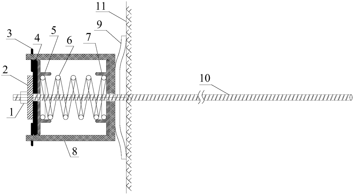
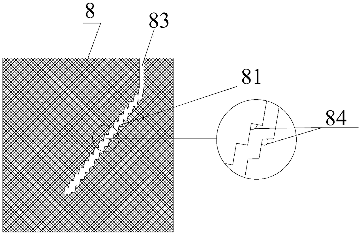
[0028] see Figure 1-4 , a timely yielding device capable of compensating for large deformations in the roadway, including a nut 1, a backing plate 2, a guide rod 3, a steering chassis 4, a second positioning ring 5, a high-strength spring 6, a first positioning ring 7, an annular cylinder 8, Tray 9, bolt body 10, wherein, 11 is surrounding rock wall of roadway. The tray 9 , the annular cylinder 8 , the steering chassis 4 and the nut 1 are in turn sleeved on the anchor body 10 along the axial direction of the anchor body 10 .

[0029] In this embodiment, the high-strength spring is an industrial high-strength and high-density compression spring made of spring steel, with an outer diameter of 80-100 mm and a steel wire diameter of 8 mm.

[0030] 6 sets of high-strength springs are arranged on the anchor rod body and are located between the steering chassis 4 and the...


PUM


Abstract

The invention discloses a timely yielding device capable of compensating large deformation of a roadway and an anchoring method of the timely yielding device. The timely yielding device comprises an anchor rod body and further comprises a tray and an annular cylinder which are outwards sequentially arranged on the anchor rod body in a sleeving mode in the axial direction; a first positioning ring,a high-strength spring, a second positioning ring, a steering chassis and a locking nut are outwards sequentially arranged on the position, located in the annular cylinder, of a rod section of the anchor rod body in a sleeving mode in the axial direction; a plurality of guiding rods are evenly distributed on the peripheral wall of the steering chassis, and guiding grooves matched with the guidingrods are formed in the side wall of the annular cylinder; and the guiding rods are mounted in the guiding grooves in a matched mode, and when the locking nut locks, the steering chassis drives the second positioning ring to axially move to compress the high-strength spring to tightly press the tray on surrounding rock. According to the timely yielding device and the anchoring method, through thecharacteristics of high resistance and large expansion and contraction quantity of the high-strength spring, controllable deformation which is allowed by the large deformation roadway is timely converted into spring compression deformation, the roadway deformation value can be measured intuitively on site, the authentic and reliable effects are achieved, and the timely yielding device and the anchoring method are suitable for supporting control over the large-deformation roadway surrounding rock existing in the complex and severe geological environment.

Description

technical field [0001] The invention belongs to the field of surrounding rock support control of mine roadways, in particular to a timely pressure relief device capable of compensating for large deformation of roadways. Background technique [0002] Through the interaction with the surrounding rock of the roadway, the conventional bolt plays a leading bearing role in the support control, bears most of the ground pressure, can prevent the loosening and damage of the surrounding rock, has a certain degree of shrinkability, and shrinks and deforms synchronously with the surrounding rock of the roadway , without losing the support ability, it is an effective support means to maintain the stability of the surrounding rock of the roadway. However, in the process of roadway excavation, complex and harsh rock formation conditions are often encountered, such as shallow buried soft rock with high geostress, soft strata in structural fracture zones, and deep mining in mines. Due to th...

Claims


Application Information

Patent Timeline
Patent Type & Authority Patents(China)
IPC IPC(8): E21D21/00E21D20/00
CPCE21D20/003E21D21/0026E21D21/0093
Inventor 李地元杜少华
Owner CENT SOUTH UNIV
Learn More