Supercharge Your Innovation With Domain-Expert AI Agents!

A fully mechanized mining hydraulic support forward moving connector

A technology of hydraulic supports and connectors, which is applied in mine roof supports, mining equipment, earthwork drilling and mining, etc. It can solve problems such as large loads, affecting the support and protection of mining working faces, and the inability to realize the axial transmission of connectors, etc.

Active Publication Date: 2021-05-07
贵州盘誉泰合机械有限公司
View PDF5 Cites 0 Cited by
  • Summary
  • Abstract
  • Description
  • Claims
  • Application Information

AI Technical Summary

Problems solved by technology

[0002] At present, when working in the fully mechanized mining face, with the progress of the mining work, the hydraulic support needs to be pushed forward through the oil cylinder. In order to ensure the safety of the entire working face, the hydraulic support needs to move forward smoothly. In the past, the hydraulic support was directly passed through the oil cylinder and the hydraulic support. When connecting, the oil cylinder directly pushes the hydraulic support to move in translation, the starting speed rises directly from 0 to the maximum, and the speed drops to 0 instantly when it stops, which makes the hydraulic support very unstable when starting and stopping, and has high requirements for the oil cylinder. The load bears is relatively large, and the existing universal joint is connected between the oil cylinder and the hydraulic support. This kind of universal joint is too flexible in the space, and the axial transmission of the joint cannot be realized under normal circumstances. When the oil cylinder The power can continue to be transmitted to the hydraulic support when the universal joint is pushed to reach the dead angle position, and the thrust of the oil cylinder is shifted under the action of the universal joint, which will cause the translation direction of the hydraulic support to shift and affect the mining face support protection

Method used


Image

  • A fully mechanized mining hydraulic support forward moving connector

Examples


Embodiment Construction

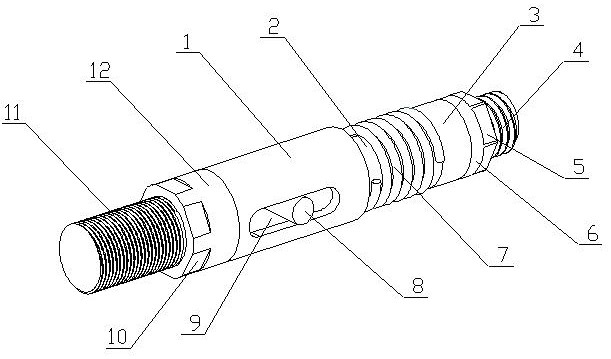
[0016] A fully-mechanized mining hydraulic support forward-moving connector of the present invention is realized in the following way: a fully-mechanized mining hydraulic support forward-moving connector of the present invention consists of a main cylinder (1), a transmission rod (2), a limit sleeve (3), a main Connecting stud (4), main six-sided fixing table (5), universal connecting sleeve (6), tension spring (7), sliding pin (8), sliding groove (9), auxiliary six-sided fixing table (10 ), an auxiliary connecting stud (11) and a rotary connecting sleeve (12), the main body cylinder (1) is provided with a sliding groove (9), the outside of the main body cylinder (1) is threaded, and the transmission rod (2 ) one end is placed in the main cylinder (1), and the other end passes through one end of the main cylinder (1), the other end of the transmission rod (2) is threaded, and one end of the sliding pin (8) is placed on the transmission rod (2) place the other end in the slidin...


PUM


Abstract

The invention discloses a fully mechanized mining hydraulic support forward-moving connecting piece, which discloses a connecting piece device that gradually changes the advancing speed and stopping speed of the hydraulic support through the buffering of springs. It can improve the stability when the hydraulic support moves. It is characterized in that there is a sliding groove on the main body cylinder, threads are provided on the outside of the main body cylinder, one end of the transmission rod is placed in the main body cylinder, and the other end passes through one end of the main body cylinder, and the other end of the transmission rod is provided with threads One end of the sliding pin is placed on the transmission rod, the other end is placed in the sliding groove, the limit sleeve is placed on the transmission rod, the tension spring sleeve is placed on the transmission rod, and is located between one end of the main cylinder and the limit sleeve. The connecting sleeve is placed on the other end of the transmission rod, and the inner wall of the universal connecting sleeve is provided with threads, which are engaged with the threads on the other end of the transmission rod. The main six-sided fixing table is placed on the universal connecting sleeve, and the main connection One end of the stud is placed on the main six-sided fixed platform, and the rotary connecting sleeve is placed on the main cylinder.

Description

technical field [0001] The invention relates to a fully-mechanized mining hydraulic support forward-moving connector, which relates to a fully-mechanized mining working face and is used to move a hydraulic support forward, and belongs to the field of mining equipment. In particular, it relates to a connecting piece device which gradually changes the advancing speed and stopping speed of the hydraulic support through the buffering of the spring. Background technique [0002] At present, when working in the fully mechanized mining face, with the progress of the mining work, the hydraulic support needs to be pushed forward through the oil cylinder. In order to ensure the safety of the entire working face, the hydraulic support needs to move forward smoothly. In the past, the hydraulic support was directly passed through the oil cylinder and the hydraulic support. When connecting, the oil cylinder directly pushes the hydraulic support to move in translation, the starting speed r...

Claims


Application Information

Patent Timeline
Patent Type & Authority Patents(China)
IPC IPC(8): E21D23/08E21D23/00
CPCE21D23/0052E21D23/08
Inventor 不公告发明人
Owner 贵州盘誉泰合机械有限公司
Features
  • R&D
  • Intellectual Property
  • Life Sciences
  • Materials
  • Tech Scout
  • Unparalleled Data Quality
  • Higher Quality Content
  • 60% Fewer Hallucinations
Learn More