Control method of antifreeze system and antifreeze system

A control method and antifreeze system technology, applied in heating systems, refrigerators, heating methods, etc., can solve problems such as inability to obtain antifreeze effects, energy consumption, and affecting user heating experience

Active Publication Date: 2020-02-14
ZHEJIANG AMA & HIEN TECH
View PDF6 Cites 0 Cited by
  • Summary
  • Abstract
  • Description
  • Claims
  • Application Information

AI Technical Summary

Problems solved by technology

[0005] Therefore, the technical problem to be solved by the present invention is to overcome the energy consumption in the antifreeze system of the floor heating system in the prior art, which cannot achieve better antifreeze effect and affects the user's heating experience.

Method used


Image

  • Control method of antifreeze system and antifreeze system
  • Control method of antifreeze system and antifreeze system
  • Control method of antifreeze system and antifreeze system

Examples


Embodiment 1

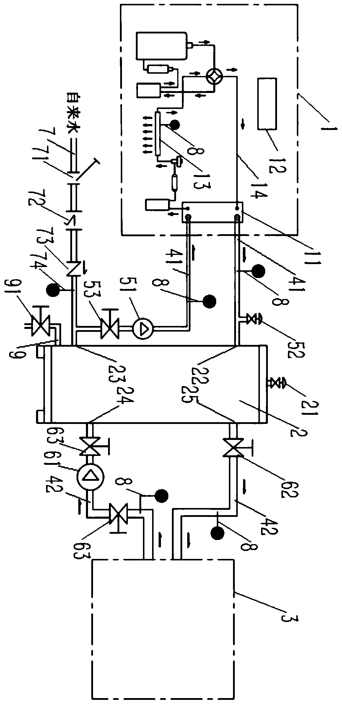
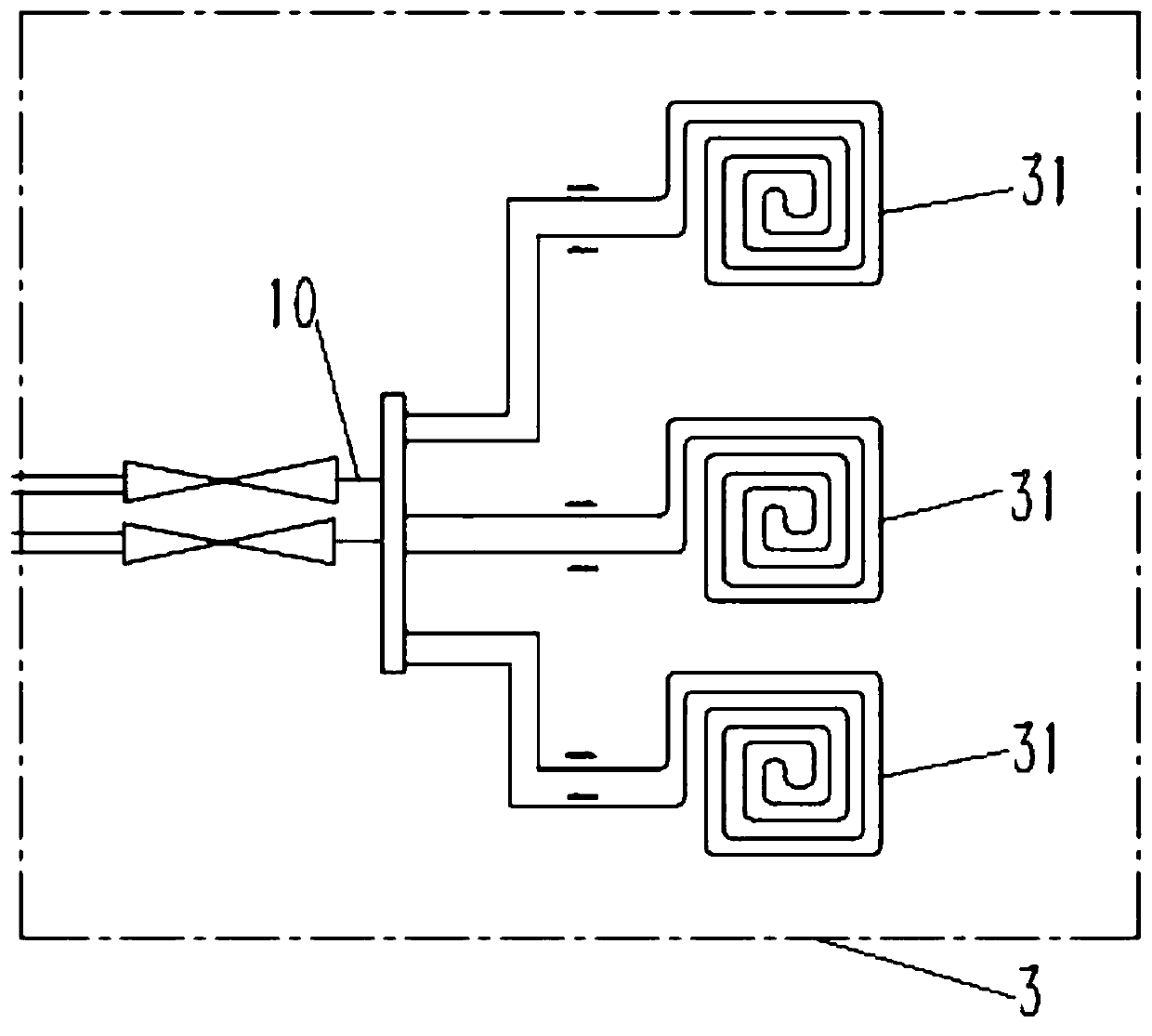
[0101] This embodiment provides an antifreeze system, such as figure 1 As shown, it includes a host 1, an incubator 2, and a heating device 3.

[0102] The main engine 1 includes a compressor, a condenser 11 , and an evaporator 13 sequentially connected through a fourth pipeline 14 , and the evaporator 13 and the compressor are connected through the fourth pipeline 14 to form a circulation loop for refrigerant circulation. That is, the cooling or heating system of the air conditioning system. The refrigerant turns from gas to liquid in the condenser and releases heat to the outside. This antifreeze system uses the heat released by the refrigerant in the condenser to heat the medium.

[0103] The evaporator 13 is provided with a first temperature detector 8 for obtaining the ambient temperature T0; the condenser 11 is preferably a plate heat exchanger, and the refrigerant releases heat through the condenser 11 to heat the medium in the condenser 11 to make the medium temperature...

Embodiment 2

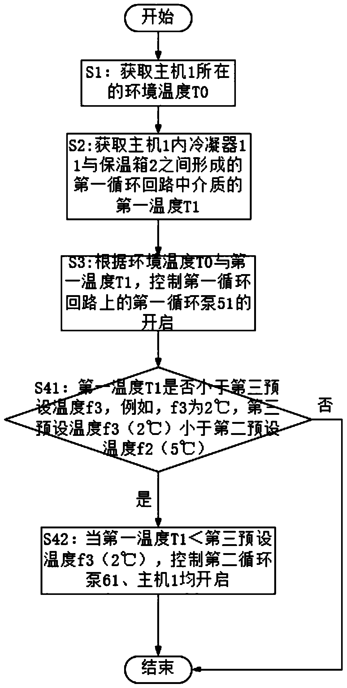
[0116] This embodiment provides a control method based on the antifreeze system provided in Embodiment 1, such as image 3 shown, including the following steps:

[0117] S1: Obtain the ambient temperature T0 where host 1 is located;

[0118] S2: Obtain the first temperature T1 of the medium in the first circulation loop formed between the condenser 11 in the host 1 and the incubator 2;

[0119] S3: According to the ambient temperature T0 and the first temperature T1, control the opening of the first circulation pump 51 on the first circulation loop. The steps are specifically:

[0120] S31: Determine whether the ambient temperature T0 is lower than the first preset temperature f1, for example, f1 is 3°C;

[0121] S32: When the ambient temperature T0 is lower than the first preset temperature f1 (3°C); then judge whether the first temperature T1 is lower than the second preset temperature f2, for example, f2 is 5°C;

[0122] S33: When the first temperature T1 is lower than ...

Embodiment 3

[0127] This embodiment provides a control method for an antifreeze system, such as Figure 4 As shown, compared with the control method of the antifreeze system provided in Example 2, the difference is that the control method of the antifreeze system can also judge whether to turn on the antifreeze system according to the third temperature T3 of the medium in the third pipeline.

[0128] S1: Obtain the ambient temperature T0 where host 1 is located;

[0129] S2: Obtain the third temperature T3 of the medium in the third pipeline 7 for supplementing the required medium in the first circulation loop;

[0130] S3: According to the ambient temperature T0 and the third temperature T3, control the opening of the first circulation pump 51 on the first circulation loop. The steps are specifically:

[0131] S31: judging whether the ambient temperature T0 is lower than the first preset temperature f1 (3° C.);

[0132] S32: When the ambient temperature T0 is lower than the first prese...


PUM


Abstract

The invention discloses an anti-freezing system control method and an anti-freezing system. The method comprises the following steps of acquiring the environment temperature where a host is located; at least acquiring a first temperature of a medium in a first circulation loop formed between a condenser in the host and a heat preservation box, a second temperature of the medium in a second circulation loop formed between the heat preservation box and a heat supply device or a third temperature of the medium in a third pipeline for supplementing the needed medium to the first circulation loop;according to the environment temperature and the first temperature or the third temperature T3, controlling the opening of a first circulation pump on the first circulation loop or according to the environment temperature T0 and the second temperature T2, controlling the opening of a second circulation pump on the second circulation loop. When the anti-freezing system is started, the anti-freezingprotection is performed according to different states of all the components, the system components are ensured not to be frozen under the low environment temperature and the energy consumption is reduced at the same time, so that a good anti-freezing effect is achieved and good heating experience is brought to a user.

Description

technical field [0001] The invention relates to the technical field of heating systems, in particular to an antifreeze control method for a floor heating system and the floor heating system. Background technique [0002] In order to control smog and adjust the energy structure, local governments represented by Beijing, Shanxi, and Tianjin have introduced government measures to reduce coal for coal and clean the air. Local governments around the world are actively promoting the use of air source heat pump equipment to replace loose coal in rural areas, which is an important measure to achieve clean air, coal reduction and coal replacement. With the successful implementation of "coal-to-electricity" in Beijing, some problems have been exposed while users have responded well. One of the problems is that the air source heat pump floor heating system is prone to pipe freezing under low ambient temperature. This not only affects the user's heating experience, but may even freeze...

Claims


Application Information

Patent Timeline
Patent Type & Authority Patents(China)
IPC IPC(8): F25B30/02
CPCF24D19/1006F24D2220/042
Inventor 郑丹庆黄元躬
Owner ZHEJIANG AMA & HIEN TECH
Why Eureka
Try Eureka