A chemical heater packaging and liquid flow tube docking device and assembly method
A chemical heater and docking device technology, applied in the direction of delayed action cells, etc., can solve problems such as large size, and achieve the effects of reducing space, avoiding electro-hydraulic residue, and shortening the length of pipelines
Active Publication Date: 2019-10-01
CHINA ELECTRONIC TECH GRP CORP NO 18 RES INST
View PDF3 Cites 0 Cited by
- Summary
- Abstract
- Description
- Claims
- Application Information
AI Technical Summary
Problems solved by technology
Currently known chemical heater packaging and liquid flow tube docking devices and methods all use welded pipe joints to connect, but the size of the connecting pipe and the nut is relatively large (more than 40mm), and the zinc-silver battery, chemical heater and liquid storage Components such as the device are installed horizontally
Method used
View moreImage
Smart ImageViewing Examples
Examples
Embodiment Construction
Login to View More PUM
 Abstract
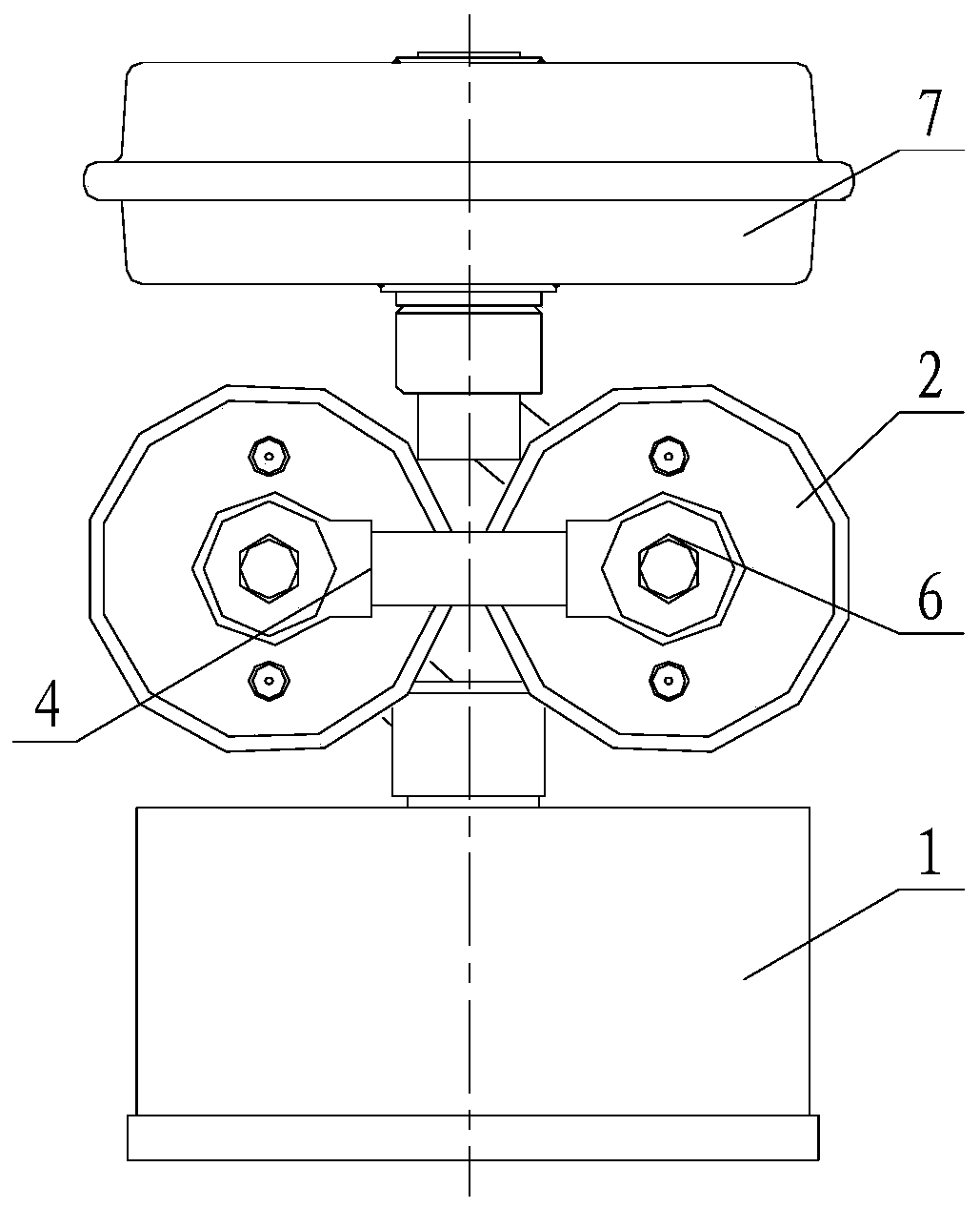
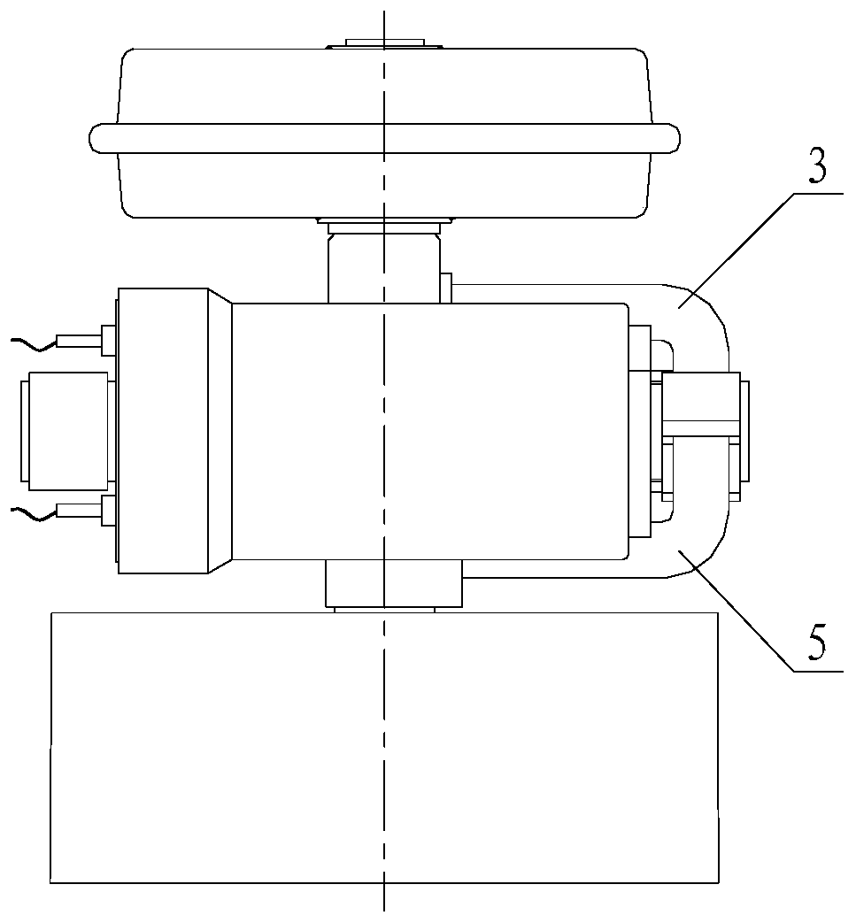
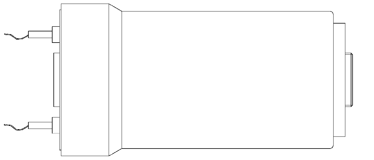
The invention discloses a chemical heater packaging and liquid flow pipe butting apparatus and assembling method. The chemical heater packaging and liquid flow pipe butting apparatus is characterizedby at least comprising two chemical heaters, a liquid reservoir positioned above the two chemical heaters and a zinc silver battery positioned below the two chemical heaters, wherein the two chemicalheaters are arranged in parallel and positioned in the same horizontal plane; the two chemical heaters include a chemical heater A and a chemical heater B; the liquid outlet of the chemical heater A and the liquid inlet of the chemical heater B are positioned on the same side; a second connecting pipe is arranged between the liquid outlet of the chemical heater A and the liquid inlet of the chemical heater B; the two ends of the second connecting pipe are connected with the two chemical heaters through compressing screws; the bottom of the liquid reservoir is connected with the liquid inlet ofthe chemical heater A through a first connecting pipe; and the liquid outlet of the chemical heater B is connected with the liquid inlet of the zinc silver battery through a third connecting pipe.
Description
technical field The invention relates to the technical field of reserve batteries and accumulators, in particular to a chemical heater packaging and liquid flow pipe butt joint device and assembly method. Background technique Zinc-silver storage batteries are widely used in various fields due to their high specific energy, high specific power, large current discharge, stable discharge voltage, high voltage accuracy, reliability and safety. Chemically heated zinc-silver reserve batteries are generally composed of battery pack casings, electrical connectors, gas generators, liquid reservoirs, combined plate sets, chemical heaters and other components. Among them, the positive and negative electrodes inside the zinc-silver reserve battery are completely isolated. When the battery pack is in use, the external DC power supply is connected through the electrical connector to provide the battery with a specified activation current, and at the same time, the electric ignition head...
Claims
Login to View More Application Information
Patent Timeline
 Patent Type & Authority Patents(China)
IPC IPC(8): H01M6/36
Inventor 关海波刘延东景义军
Owner CHINA ELECTRONIC TECH GRP CORP NO 18 RES INST
Features
- R&D
- Intellectual Property
- Life Sciences
- Materials
- Tech Scout
- Unparalleled Data Quality
- Higher Quality Content
- 60% Fewer Hallucinations
Learn More Browse by: Latest US Patents, China's latest patents, Technical Efficacy Thesaurus, Application Domain, Technology Topic, Popular Technical Reports.
© 2025 PatSnap. All rights reserved.Legal|Privacy policy|Modern Slavery Act Transparency Statement|Sitemap|About US| Contact US: help@patsnap.com


