
Terminal and telephone receiver thereof

A receiver and terminal technology, applied in the electronic field, can solve the problems of long terminal length, affecting the appearance of the whole machine, and large size, so as to achieve the effect of reducing size and improving aesthetics

Active Publication Date: 2014-02-12
HUIZHOU TCL MOBILE COMM CO LTD
View PDF3 Cites 11 Cited by
  • Summary
  • Abstract
  • Description
  • Claims
  • Application Information

AI Technical Summary

Problems solved by technology

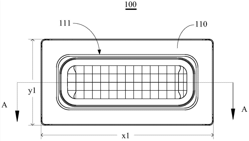
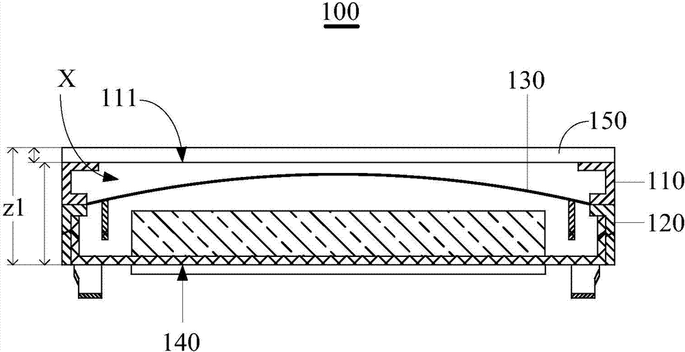
However, the larger planar area of ​​the front cover 110 will inevitably lead to a larger width of the receiver 100, thereby resulting in a larger size occupied by it in the length direction of the terminal, which will easily cause the length of the terminal to be too long and not commensurate with its width. Affect the appearance of the whole machine

Method used


Image

  • Terminal and telephone receiver thereof
  • Terminal and telephone receiver thereof
  • Terminal and telephone receiver thereof

Examples


Embodiment Construction

[0022] Attached below Figure 1-7 The technical solution of the present invention is introduced in detail with specific embodiments.

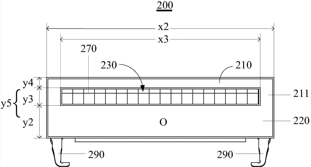
[0023] image 3 It is a schematic diagram of the front structure of an embodiment of the receiver of the present invention, Figure 4 yes image 3 A top view of the receiver shown, Figure 5 yes Figure 4 The cross-sectional view of the shown receiver along the B-B direction, that is image 3 cross-sectional view. combine image 3 , Figure 4 and Figure 5 As shown, the receiver 200 of this embodiment includes a first cover 210 , a second cover 220 , a sound hole 230 , a diaphragm 240 , a magnetic circuit module 250 and a voice coil 260 .

[0024] Wherein, the first cover 210 is provided with sealing ribs 211 , and the first cover 210 is fixed to the second cover 220 through the sealing ribs 211 , so as to cooperate to form the acoustic cavity B of the receiver 200 . In actual implementation, in this embodiment, the first cover 210 an...


PUM


Abstract

The invention provides a terminal and a telephone receiver of the terminal. The telephone receiver comprises a first cover body, a second cover body, a vibrating diaphragm and voice outlet holes. The vibrating diaphragm is arranged between the first cover body and the second cover body. A voice cavity is formed by the first cover body and the second cover body in a matched mode and comprises a front voice cavity and a rear voice cavity, wherein the front voice cavity is defined by the vibrating diaphragm and the first cover body, and the rear voice cavity is defined by the vibrating diaphragm and the second cover body. The voice outlet holes are formed in the joint of the first cover body and the second voice body, aligned with loudspeaking holes of the terminal and clamped between the first cover body and the plane where the vibrating diaphragm is located. In this way, when the telephone receiver is installed on the terminal, space, occupied by the telephone receiver, in the length direction of the terminal can be reduced.

Description

technical field [0001] The invention relates to the field of electronic technology, in particular to a terminal and a receiver thereof. Background technique [0002] The receiver is an electroacoustic device that converts electrical signals into sound. According to its working principle, it can be divided into carbon crystal type, capacitive type, moving iron type and moving coil type. At present, dynamic receivers have been widely used in terminal technology fields such as smartphones. [0003] figure 1 It is a schematic diagram of the front structure of the receiver in the prior art, figure 2 yes figure 1 A cross-sectional view of the receiver shown along the direction A-A. refer to figure 1 and figure 2 , the front cover 110 and the rear cover 120 cooperate to define the sound cavity X of the receiver 100 , and the sound outlet 111 is opened on the front cover 110 of the receiver 100 . When the receiver 100 is installed on a terminal such as a smart phone, since ...

Claims


Application Information

Patent Timeline
Patent Type & Authority Applications(China)
IPC IPC(8): H04R9/10H04R9/02H04M1/03
Inventor 魏金平欧妍平张庆峰
Owner HUIZHOU TCL MOBILE COMM CO LTD
Learn More